Drilling machine structure for geothermal well drilling

A geothermal drilling and drilling rig technology, applied in drilling equipment, earthmoving, wellbore/well components, etc., can solve the problems of bulky sound insulation cover, lack of wellhead mechanized tools, high labor intensity, etc., and achieve compact layout , reduce the source of pollution, reduce the effect of noise pollution

Active Publication Date: 2016-09-28
INST OF SINOPEC OILFIELD EQUIP CORP +1
View PDF10 Cites 2 Cited by
  • Summary
  • Abstract
  • Description
  • Claims
  • Application Information

AI Technical Summary

Problems solved by technology

[0004] At present, domestic geothermal well drilling rigs generally use old-fashioned oil drilling rigs or simple and relatively backward water well drilling rigs. They only simplify the configuration of the equipment and do not pursue the advanced nature of the equipment. Most of them use mechanical transmission structures, which have low operating efficiency and high noise. HSE requirements are not strict, pre-drilling preparation takes a long time, lack of wellhead mechanized tools, labor intensity is high, and there are potential safety hazards, which cannot effectively meet the requirements of geothermal drilling in terms of improving efficiency, enhancing regional adaptability, and reducing costs.
Moreover, the existing noise reduction measures are to shield the noise source with a sound-proof cover. The traditional sound-proof cover has a bulky structure and a single form. Its sound insulation effect is not good and it is not easy to disassemble and repair the equipment. Due to the requirements of geothermal drilling in residential areas, this also affects the application and development of domestic geothermal drilling technology to a certain extent.

Method used


Image

  • Drilling machine structure for geothermal well drilling
  • Drilling machine structure for geothermal well drilling
  • Drilling machine structure for geothermal well drilling

Examples


Embodiment Construction

[0040] The present invention will be further described in detail below in conjunction with the accompanying drawings, so that those skilled in the art can implement it with reference to the description.

[0041] It should be understood that terms such as "having", "comprising" and "including" as used herein do not entail the presence or addition of one or more other elements or combinations thereof.

[0042] In the description of the invention, the orientation or positional relationship indicated by the terms "upper", "middle", "lower", "top", "bottom", "inner", "outer" etc. is based on the orientation or positional relationship shown in the drawings The positional relationship is only for the convenience of describing the present invention and simplifying the description, and does not indicate or imply that the referred device or element must have a specific orientation, be constructed and operated in a specific orientation, and thus should not be construed as limiting the pre...


PUM


Abstract

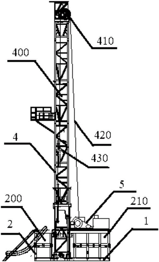
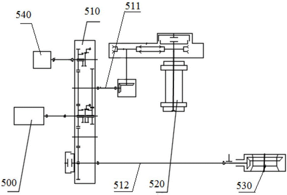
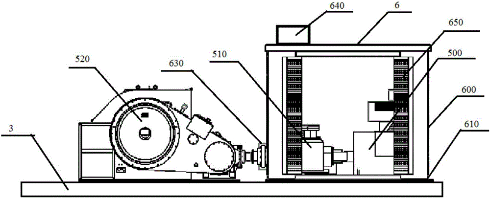
The invention discloses a drilling machine structure for geothermal well drilling. The drilling machine structure comprises a base, a container, a derrick, a power transmission system and a noise reduction device, wherein the container comprises a front container body and a rear container body; the derrick is an upright sleeved self-elevating derrick; the power transmission system comprises a main motor, a transfer case, a first power output shaft, a second power output shaft, a roller and a rotary plate; the noise reduction device comprises an acoustic shield and a damping base, so that an accommodating space used for accommodating the main motor and the transfer case is formed; the main motor and the transfer case are sequentially mounted on the damping base in the direction close to the derrick; a sledding base is mounted at the top of the rear container body; and the noise reduction device and the roller are both mounted on the sledding base. The modularized design is adopted, and the drilling machine structure has the beneficial effects of being small in occupied area and noise pollution, high in transfer efficiency, low in operation cost, and suitable for geothermal well drilling operation in residential communities.

Description

technical field [0001] The invention relates to the field of drilling rigs. More specifically, the present invention relates to a geothermal drilling rig structure with good sound insulation effect and modular design. Background technique [0002] Geothermal energy is a kind of energy from the interior of the earth. my country's medium and low temperature geothermal resources are found in more than 30 provinces, cities and autonomous regions across the country. The market potential is huge, and its development prospects are very broad. [0003] Medium and low temperature geothermal wells are mostly drilled in residential areas, and the well site area is small, requiring low noise during drilling; the tripping frequency is low during the drilling process, requiring rapid drilling and completion, shortening the well construction period; and low operating costs. [0004] At present, the geothermal well drilling rigs currently in use in China generally use old-fashioned oil dri...

Claims


Application Information

Patent Timeline
Patent Type & Authority Applications(China)
IPC IPC(8): E21B15/00E21B41/00
CPCE21B15/00E21B41/00
Inventor 黎爱军屈晓妮池胜高周斌沈珍平信石玉李超
Owner INST OF SINOPEC OILFIELD EQUIP CORP
Why Eureka
Try Eureka