Low-nitrogen burner

A gas and mixer technology, which is applied in the direction of burners, gas fuel burners, combustion methods, etc., can solve the problems that the mixing effect is not in the best state, and the theoretical air-fuel ratio cannot be mixed, so as to reduce the excess air coefficient and stabilize combustion , the effect of strong flame rigidity

Active Publication Date: 2016-09-28
BEIJING SHENKEBOSI THERMAL ENERGY ENG TECH CO LTD
View PDF8 Cites 17 Cited by
  • Summary
  • Abstract
  • Description
  • Claims
  • Application Information

AI Technical Summary

Problems solved by technology

[0002] At present, the Chinese patent publication No. 102913909A discloses a metal fiber post-mixing burner, which includes a combustion head, a fan and a mixer; the mixer is provided with a gas inlet; the gas swirl device includes at least two swirls Flow sheet, the swirl sheet is stretched by a hollow ring, the diameter of the hollow part of the swirl sheet is smaller than the diameter of the combustion head, and one of the swirl sheets is arranged obliquely close to the gas inlet, and the It is the leeward side of the fan supply air, so that the gas and air in the mixer form a swirl and fully mix; when working, the gas and the air sent into the mixer by the fan flow into the mixer, and pass through the gas swirl device After fully mixing, this gas swirl device only passes the gas at the gas inlet through the swirl plate as a guide for mixing. The whole process has only one mixing process, and the mixing effect is not optimal, resulting in the inability to mix to achieve the theoretical air-fuel ratio of complete combustion.

Method used


Image

  • Low-nitrogen burner
  • Low-nitrogen burner
  • Low-nitrogen burner

Examples


Embodiment 1

[0037] Embodiment 1: a kind of mixer, such as Figure 5 As shown, it includes a cylinder body 22 and a gas inlet 12 arranged on the peripheral wall of the cylinder body 22. The two axial ends of the cylinder body 22 are respectively set against the inlet flange 24 and the outlet flange 25. In the air flow direction, there is a gas inlet 12 along the side of the inlet flange 24 in the cylinder body 22, and a snap ring 211 is fixedly connected to the inner wall of the cylinder body 22 along the side of the outlet flange 25, and the snap ring 211 is connected to the cylinder body. 22 coaxial, the circumference of the snap ring 211 is provided with a fixed shaft 212 coaxial with the cylinder 22, and the two ends of the fixed shaft 212 are respectively fixed with a primary swirl impeller 19 and a secondary swirl impeller 20 of the same shape.

[0038] combine 4, Figure 5 , the cylinder 22 is located in the gas sub-cavity 13 and is provided with an inner cylinder 17, and the inter...

Embodiment 2

[0043] Embodiment 2: a kind of mixer, the difference with embodiment 1 is that the vane 192 of the combustion-supporting air swirl plate 14 is right-handed according to the air inlet direction of the air flow, and the primary swirl impeller 19 and the secondary swirl vane are according to The air inlet direction of the airflow is left-handed.

Embodiment 3

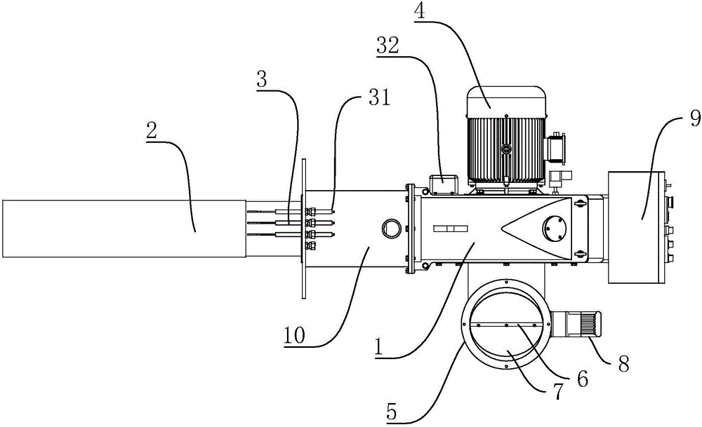
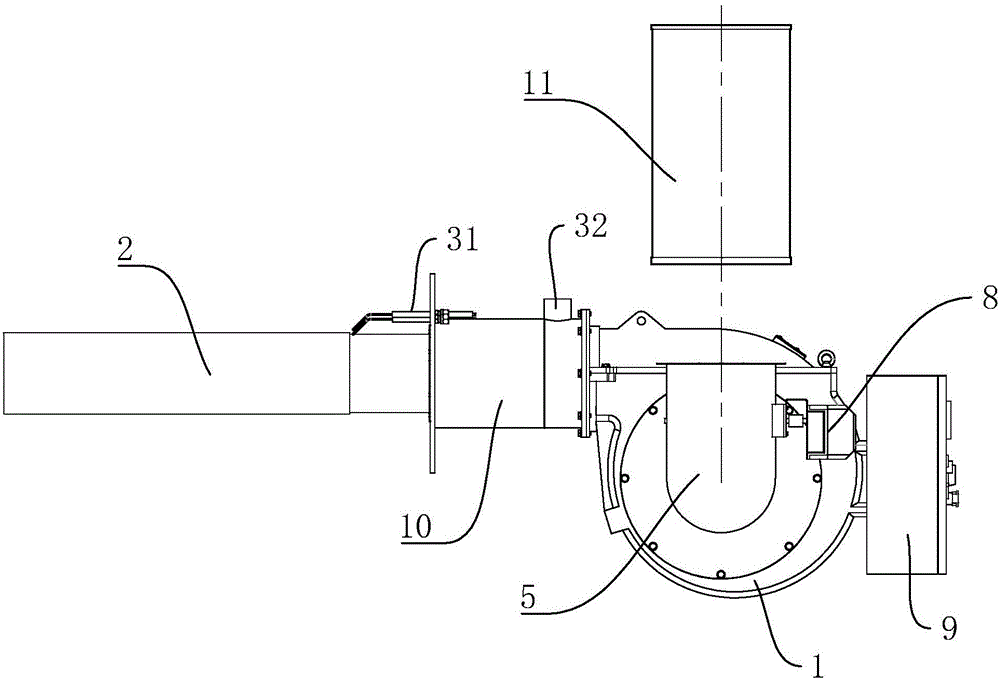
[0044] Embodiment 3: a kind of low nitrogen burner, such as figure 1 and figure 2 As shown, it includes a combustion head 2, an ignition device 3, a fan 1, a motor of the fan 1, a control cabinet 9 and the mixer 10 in Embodiment 1, and the control cabinet 9 has a PLC controller.

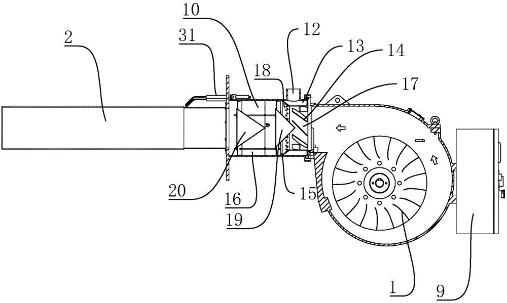
[0045] refer to image 3 , the barrel 22 of the mixer 10 is connected to the fan 1, the fan 1 includes the fan 1 casing and the fan 1 impeller, the outer ring of the fan 1 impeller is tangent to the axis of the barrel 22, and when the fan 1 impeller rotates, the wind flow is generated along the direction of the casing. The arc-shaped inner wall enters the inside of the barrel 22, and the outlet flange of the barrel 22 is connected to the combustion head 2. The combustion head 2 is a metal fiber combustion head. Specifically, the outer surface of the combustion head is provided with a metal fiber felt, and the metal fiber combustion head The technical application power ranges from 5kW to 40,000kW, ...


PUM


Abstract

The invention discloses a low-nitrogen burner. According to the technical scheme, the low-nitrogen burner is characterized in that a mixer of the low-nitrogen burner comprises a barrel and a gas inlet, wherein an inner barrel and burning-supporting air swirling pieces arranged on the inner wall of the inner barrel are arranged at the gas inlet front end inside the barrel; an air inlet barrel located on the back side of the burning-supporting air swirling pieces in the air inlet direction is arranged at one end, close to the gas inlet back side, of the inner barrel; the air inlet barrel, the inner barrel and the inner wall of the barrel are connected in a sealed manner to form a gas sub-cavity; inclined flow guiding holes are formed in the air inlet barrel; a primary swirling impeller is arranged in the position, located on the air inlet back side of the inner barrel, inside the barrel; and the primary swirling impeller and the air inlet barrel form a primary mixing chamber. Through the arrangement, gas is ejected via the gas sub-cavity from the inclined flow guiding holes, the ejected gas can form multiple single, short and powerful gas flows, air flows sent by a fan pass through the burning-supporting air swirling pieces to form short and powerful rotating air flows, and the rotating air flows are circular and impact the multiple single gas flows, so that the air and the gas of the primary mixed gas reach the air-fuel ratio in the complete burning theory.

Description

technical field [0001] The invention relates to the field of gas fuel burners, in particular to a low-nitrogen burner. Background technique [0002] At present, the Chinese patent publication No. 102913909A discloses a metal fiber post-mixing burner, which includes a combustion head, a fan and a mixer; the mixer is provided with a gas inlet; the gas swirl device includes at least two swirls Flow sheet, the swirl sheet is stretched by a hollow ring, the diameter of the hollow part of the swirl sheet is smaller than the diameter of the combustion head, and one of the swirl sheets is arranged obliquely close to the gas inlet, and the It is the leeward side of the fan supply air, so that the gas and air in the mixer form a swirl and fully mix; when working, the gas and the air sent into the mixer by the fan flow into the mixer, and pass through the gas swirl device After full mixing, this gas swirl device only passes the gas at the gas inlet through the swirl plate as a guide f...

Claims


Application Information

Patent Timeline
Patent Type & Authority Applications(China)
IPC IPC(8): F23D14/02F23D14/62F23D14/46
CPCF23D14/02F23D14/46F23D14/62
Inventor 王鸿川李亚运王德义王国政
Owner BEIJING SHENKEBOSI THERMAL ENERGY ENG TECH CO LTD
Why Eureka
Try Eureka