
Vertical U-shaped gasification heating equipment

A kind of heating equipment, U-shaped technology, applied in the field of heating and gasification, can solve the problems of poor economic and environmental protection, low air heat capacity, high cost, etc., achieve the effect of convenient gas-water separation, high thermal efficiency, and reduce heat consumption

Active Publication Date: 2020-10-16
SHANGHAI UNIV OF ENG SCI
View PDF5 Cites 0 Cited by
  • Summary
  • Abstract
  • Description
  • Claims
  • Application Information

AI Technical Summary

Problems solved by technology

Most of these gasification devices are used for LNG heating, and there are some limitations, for example: the cost of water heating gasification device is relatively high, only suitable for some large gas heating plants, and the economy is poor; air heating type gasification The disadvantage of the device is that it uses air heating, the air heat capacity is low, the energy required for heating is relatively large, and the economy and environmental protection are poor.

Method used


Image

  • Vertical U-shaped gasification heating equipment
  • Vertical U-shaped gasification heating equipment

Examples


Embodiment 1

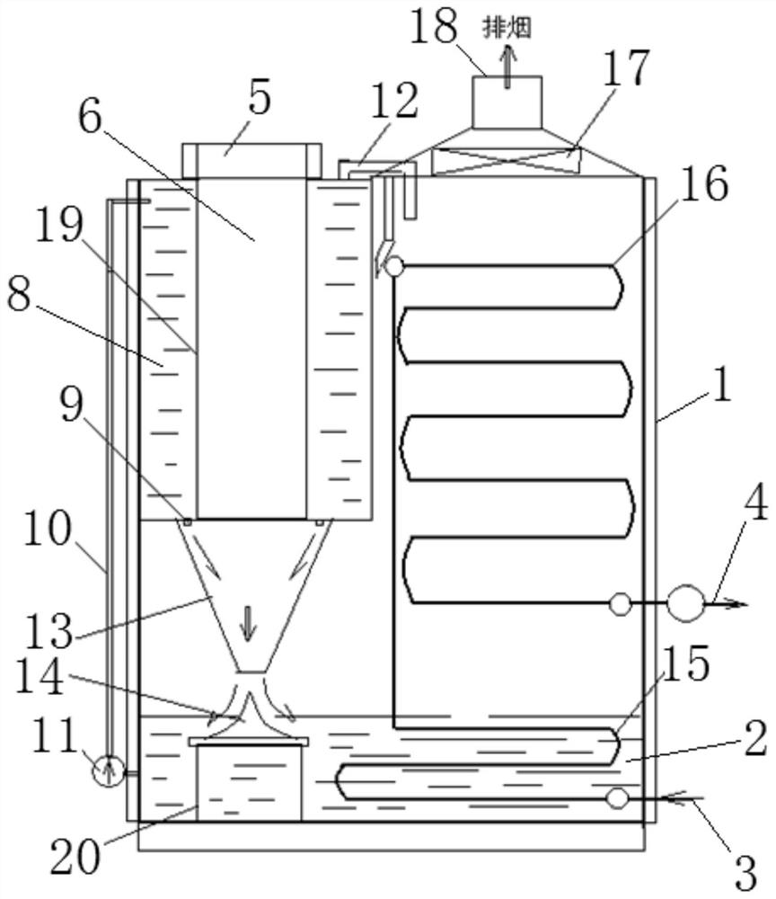
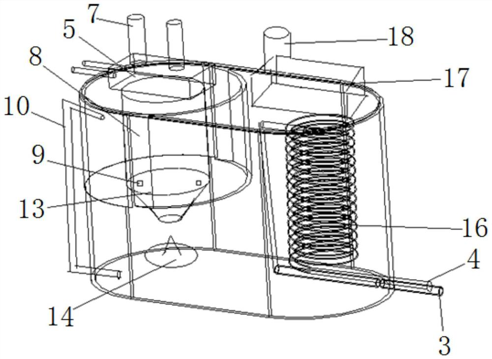
[0031] Such as figure 1 , figure 2In the shown vertical peak-shaving U-shaped gasification heating equipment, the fuel enters the burner 5 through the fuel inlet 7, the burner 5 is started, the fuel is fully burned in the combustion chamber 6, and a large amount of smoke is generated. And spray out at the nozzle 13, the water chamber 8 protects the combustion chamber 6, and prevents the equipment from being damaged due to too high temperature. The water in the water chamber 8 absorbs the waste heat of the combustion chamber 6, reaches the water nozzle 9, the water at the water nozzle 9 enters the nozzle 13, mixes the high-temperature flue gas to become water smoke, and reaches the guide plate 14, the guide plate 14 It plays the role of buffering the flue gas, and also has the function of drainage to increase the contact area. The water in the bottom pool 2 is successfully gasified, and the gasified water vapor reaches the heated pipe 16 on the right side together with the fl...

Embodiment 2

[0033] The utility model relates to a vertical U-shaped gasification heating device, which is used for heating industrial gas or industrial liquid. The equipment includes a housing 1, a bottom pool 2 arranged in the housing 1, and a heat source unit and a heated unit arranged side by side in the housing 1. The bottoms of the heat source unit and the heated unit are located in the bottom pool 2. The heat source unit includes The combustion mechanism and the injection guide mechanism are respectively arranged one above the other. The side of the housing 1 is provided with a fluid inlet 3 and a fluid outlet 4. The heated unit is connected with the fluid inlet 3 and the fluid outlet 4 respectively. Smoke extraction unit.

[0034] Wherein, the combustion mechanism includes a burner 5 arranged on the top of the housing 1 and a torch 19 arranged below the burner 5, the inside of the torch 19 is provided with a combustion chamber 6, the burner 5 is provided with a fuel inlet 7, and th...


PUM


Abstract

The invention relates to vertical U-shaped gasification heating equipment. The equipment comprises a shell, a bottom water pool arranged in the shell and a heat source unit and a heated unit arrangedin the shell side by side, wherein the bottoms of the heat source unit and the heated unit are located in the bottom water pool, the heat source unit comprises a combustion mechanism and an injectionguide mechanism which are arranged up and down respectively, a fluid inlet and a fluid outlet are formed in the side face of the shell, the heated unit communicates with the fluid inlet and the fluidoutlet, and a smoke exhaust unit is arranged above the heated unit. Compared with the prior art, the equipment can be used for heating industrial gas or industrial liquid, is wide in application range, increases a heat exchange rate, improves an energy utilization rate, and has a peak regulation effect, so that the equipment is higher in working usability, economical and convenient.

Description

technical field [0001] The invention belongs to the technical field of heating and gasification, and relates to a vertical peak-shaving U-shaped gasification heating device. Background technique [0002] With the development of China's economy, the mining, transportation and efficient utilization of energy are becoming more and more important, and the status of environmentally friendly fuels is also increasing. Therefore, the efficient and environmentally friendly utilization of energy is the current development trend and a necessary choice. [0003] At present, there are mainly the following types of heating gasification devices: 1. Water heating gasification device; 2. Submerged combustion heating type gasification device; 3. Air heating type gasification device; 4. Intermediate heat transfer medium type gasification device ; 5. Steam heating gasification device. Most of these gasification devices are used for LNG heating, and there are some limitations, for example: the ...

Claims


Application Information

Patent Timeline
Patent Type & Authority Applications(China)
IPC IPC(8): F24H7/02F24H9/18F28C3/08F28D7/08F28B9/08F17C7/04
CPCF24H7/025F24H9/1836F28C3/08F28D7/082F28B9/08F17C7/04Y02P20/10
Inventor 郭韵陈昊
Owner SHANGHAI UNIV OF ENG SCI
Learn More