
Illuminating film structure

A lighting film and film structure technology, applied in lighting devices, lighting and heating equipment, printed circuits, etc., can solve problems such as the limitation of lighting surface flexibility, and achieve the effect of flexibility and thickness improvement

Inactive Publication Date: 2016-09-28
FLEXBRIGHT
View PDF8 Cites 4 Cited by
  • Summary
  • Abstract
  • Description
  • Claims
  • Application Information

AI Technical Summary

Problems solved by technology

This overall thickness leads to an absolute limit on the flexibility of the illuminated surface

Method used


Image

  • Illuminating film structure
  • Illuminating film structure
  • Illuminating film structure

Examples


Embodiment Construction

[0020] The following embodiments are merely examples. Although this specification may refer to "one" embodiment in several places, this does not necessarily mean that each such reference is to the same embodiment(s) or that a feature is only applicable to a single embodiment. Single features of different embodiments may also be combined to provide other embodiments. Furthermore, the words "comprising" and "comprising" should not be understood as limiting the described embodiments to consist of only those features that have been mentioned, and such embodiments may also contain features / structures that have not been specifically mentioned.

[0021] It should be noted that while the figures illustrate various embodiments, they are simplified and only show some structural and / or functional entities. Connections shown in the figures may refer to electrical and / or physical connections. It will be clear to those skilled in the art that the described devices may also include other f...


PUM

PropertyMeasurementUnit
thicknessaaaaaaaaaa
luminanceaaaaaaaaaa

Abstract

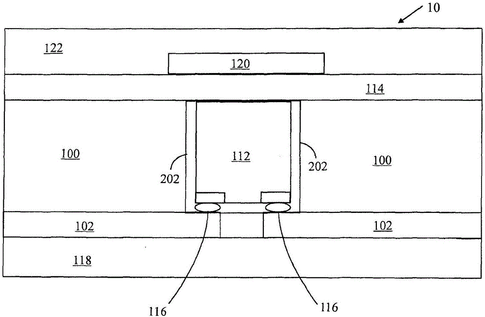
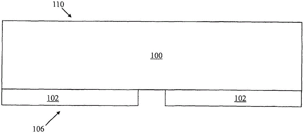
A flexible and illuminating film structure wherein the flexible and illuminating film structure (10) comprises a flexible single polymer foil (100); a flexible electrically conductive pattern layer (102) with contact areas (104) for components on a first side (106) of the polymer foil (100); at least one cavity (108) which extends though the polymer foil (100) from a second side (110) to the contact areas (104) of the conductive pattern layer (102) on the first side (106) and overlaps with at least one contact area (104); at least one non-organic light emitting diode flip-chip (112) in the at least one cavity (108) and electrically coupled with the contact areas (104); and a first flexible shielding foil (114) layered on the second side (110) of the polymer foil (100).

Description

technical field [0001] The present invention relates to lighting film structures. Background technique [0002] Organic LEDs or OLEDs offer the possibility of producing relatively thin lighting films which can in principle be flexible. However, organic materials require very good protection against ambient oxygen and moisture in order to have a sufficiently long life expectancy from a practical point of view. That's why OLEDs are enclosed between two glass plates, which results in a loss of thinness and flexibility. [0003] During the manufacture of SMD (Surface Mount Device) LEDs (Light Emitting Diodes), components and even bare chips can be bonded on the surface of a polymer substrate for relatively thin lighting that is somewhat flexible structure. The overall thickness of the structure is primarily determined by the sum of the thickness of the LED device and the thickness of the polymer substrate(s). This total thickness leads to an absolute limit on the flexibility...

Claims


Application Information

Patent Timeline
Patent Type & Authority Applications(China)
IPC IPC(8): F21S4/22H05K1/18
CPCH05K1/092H05K1/095H05K1/183H05K1/186H05K1/189H05K3/281H05K3/321H05K2201/10106H05K2201/10674H05K2201/2054H01L2224/16225H01L25/0753H01L33/502H01L33/56H01L33/60H01L33/62H01L2933/0041H01L2933/005H01L2933/0058H01L2933/0066H05K1/028H05K9/0073
Inventor P·马库南K·凯拉南
Owner FLEXBRIGHT
Learn More