
Ammonia neutralization device

A technology of reaction gas and inlet, applied in chemical instruments and methods, dispersed particle separation, air quality improvement, etc., can solve the problems of shortened operation cycle, low ammonia removal rate, increased organic polymer loss, etc., and achieves reduction of shutdown cleaning. Frequency, uniform gas-liquid contact, and the effect of improving the quenching effect

Inactive Publication Date: 2016-10-05
CHINA PETROLEUM & CHEM CORP +1
View PDF8 Cites 0 Cited by
  • Summary
  • Abstract
  • Description
  • Claims
  • Application Information

AI Technical Summary

Problems solved by technology

[0004] One of the technical problems to be solved by the present invention is that the removal rate of ammonia in the reaction gas in the ammonia neutralization device in the prior art is low, ammonia enters the follow-up system, increases the polymer loss of organic matter, and causes blockage of towers and pipelines , to shorten the operation period of the device, and provide a new ammonia neutralization device
[0005] The second technical problem to be solved by the present invention is that the neutralization method of ammonia in the ammoxidation reaction existing in the prior art is unreasonable, the removal efficiency of ammonia is not high, and ammonia enters subsequent towers, heat exchangers and pipeline systems, resulting in subsequent Provide a new ammonia neutralization method for the problems of equipment and pipeline blockage, increased device consumption, and shortened operating cycle

Method used


Image

  • Ammonia neutralization device

Examples


Embodiment 1

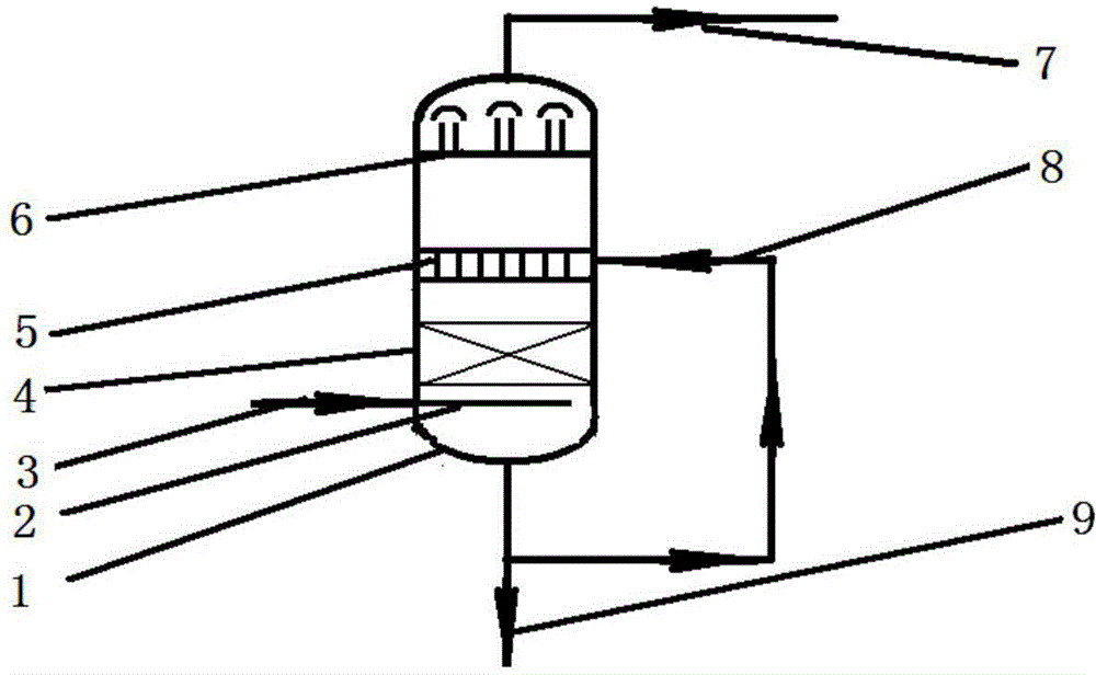
[0027] An ammonia neutralization device, below the reaction gas neutralizing liquid inlet and above the reaction gas inlet, two theoretical plate grid fillers are arranged, and four layers of reaction gas center composed of hollow cone nozzles arranged in a square are arranged in the neutralization device. And liquid spray layer, the arrangement density of nozzles is 2 nozzles / m 2, the reaction gas inlet is equipped with a dendritic porous gas distributor, and two theoretical bubble cap plates are set above the spray layer as a demister. After neutralization, the removal rate of ammonia in the reaction gas reaches 99.9%. There is no blockage in the device and subsequent systems, the heat exchange effect of the heat exchanger and the system resistance remain unchanged, the polymerization loss of organic matter is reduced, and the operating cycle of the device reaches 18 months, which prolongs the operating cycle of the device and achieves better technical results.

Embodiment 2

[0029] An ammonia neutralization device, the ammonia neutralization device includes a shell, a reaction gas inlet and a reaction gas outlet, a reaction gas neutralization liquid inlet and a reaction gas neutralization liquid outlet, the reaction gas inlet is arranged at the lower part of the ammonia neutralization device, and the reaction gas The outlet is arranged at the top of the ammonia neutralization device, the inlet of the reaction gas neutralization liquid is arranged above the inlet of the reaction gas, the outlet of the neutralization liquid is arranged at the bottom of the ammonia neutralization device, and below the inlet of the reaction gas neutralization liquid in the ammonia neutralization device, the reaction gas A tray or packing is arranged above the inlet, and a multi-layer spray layer composed of nozzles arranged according to geometric shapes is arranged at the inlet of the reaction gas neutralization liquid. Demister; under the demister, there are 2 spray l...

Embodiment 3

[0033] The neutralization device includes a shell, a reaction gas inlet and a reaction gas outlet, a reaction gas neutralization liquid inlet and a reaction gas neutralization liquid outlet, the reaction gas inlet is set at the lower part of the ammonia neutralization device, and the reaction gas outlet is set at the top of the ammonia neutralization device , the inlet of the reaction gas neutralizing liquid is set above the inlet of the reaction gas, and the outlet of the neutralizing liquid is set at the bottom of the ammonia neutralization device, wherein trays or packing are arranged below the inlet of the reaction gas neutralizing liquid and above the inlet of the reaction gas in the ammonia neutralization device , and the inlet of the neutralizing liquid is provided with a liquid distributor.

[0034] A demister is arranged above the inlet of the reaction gas neutralizing liquid; a spray layer spraying upward is arranged below the demister.

[0035] Each spray layer is p...


PUM


Abstract

The invention relates to an ammonia neutralization device. The ammonia neutralization device is mainly used for solving the problems in the prior art that the rate of removal of ammonia from reactant gases in an ammonia oxidation reaction is low, the ammonia enters a subsequent system, the polymer loss of organic matters is increased, the clogging to towers and pipelines is caused, and the operation cycle of equipment is shortened. According to the ammonia neutralization device, by adopting the technical scheme that the ammonia neutralization device comprises a shell, a reactant gas inlet, a reactant gas outlet, a reactant gas neutralizing solution inlet and a reactant gas neutralizing solution outlet, a tower plate or filler which is located below the reactant gas neutralizing solution inlet and above the reactant gas inlet is arranged in the ammonia neutralization device, multiple spraying layers which are formed by sprayers in a manner of being distributed in a geometric shape are arranged at the reactant gas neutralizing solution inlet, a reactant gas neutralizing solution is in counter-flow contact with the reactant gases, and a demister is arranged above the reactant gas neutralizing solution inlet, the problems are better solved, and thus the ammonia neutralization device can be applied to an industrial unit for the ammonia oxidation reaction.

Description

technical field [0001] The invention relates to an ammonia neutralization device. Background technique [0002] In the ammoxidation reaction device, the reaction gas at the outlet of the fluidized bed reactor contains unreacted ammonia, which must be removed as soon as possible, and the removal must be thorough, otherwise the ammonia entering the subsequent system will cause the pH value of the system to increase, resulting in increased product loss. It affects the recovery rate of the product, and also causes polymer blockage in towers, heat exchangers, pipelines, etc., affecting the normal operation of the device. At present, multi-layer spray layers are used to neutralize ammonia, the gas-liquid contact is insufficient, and the removal efficiency of ammonia is not high. The consumption has very important practical significance and economic benefits. [0003] Document US3885928 has introduced a kind of recovery and refining system of alkenonitrile, wherein the purpose of...

Claims


Application Information

Patent Timeline
IPC IPC(8): B01D53/78B01D53/58
CPCY02A50/20
Inventor 顾军民熊瑾
Owner CHINA PETROLEUM & CHEM CORP
Learn More