Decarburization method adopting diethyl carbonate as absorbent

A technology of diethyl carbonate and absorbent, applied in the field of chemical engineering, can solve the problems of small absorption capacity of absorbent, large investment in equipment, long process flow, etc., and achieve the effects of reducing energy consumption, equipment investment and solvent price

Inactive Publication Date: 2013-06-05
TSINGHUA UNIV
View PDF7 Cites 0 Cited by
  • Summary
  • Abstract
  • Description
  • Claims
  • Application Information

AI Technical Summary

Problems solved by technology

[0006] In view of the shortcomings and defects of the existing low-temperature methanol washing method, which have long process flow, large equipment investment, small absorption capacity of absorbent in the propylene carbonate method, large circulation volume, high cost of polyethylene glycol dimethyl ether method, and prone to polymerization loss, The invention provides a decarburization method using diethyl carbonate as an absorbent to further simplify the process and reduce costs

Method used


Image

  • Decarburization method adopting diethyl carbonate as absorbent
  • Decarburization method adopting diethyl carbonate as absorbent
  • Decarburization method adopting diethyl carbonate as absorbent

Examples


Embodiment 1

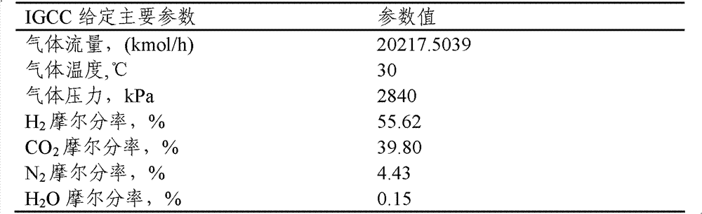
[0026] Contains CO 2 The mixed gas, temperature 30 ℃, pressure 2800KPa, composition (mol fraction) as shown in Table 1:

[0027] Table 1 Feed gas flow rate and composition

[0028]

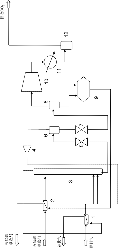
[0029] CO removal with absorber overhead 2 After heat exchange, the purified gas is lowered to 20°C and enters the absorption tower from the lower part, and the diethyl carbonate from the absorbent storage tank at 25°C exchanges heat with the desorbed circulating absorbent lean liquid and enters the absorption tower from the upper part after heat exchange to 5°C. The agent flow rate is 36809.15kmol / h. The two phases of gas and liquid are in countercurrent contact in the tower and absorption and mass transfer occur. The temperature at the top of the absorption tower is 21°C and the pressure is 2800KPa; the temperature at the bottom of the tower is 26°C and the pressure is 2840KPa. CO removal 2 After heat exchange between the purified gas and the raw material gas, the temperature is lowered ...

Embodiment 2

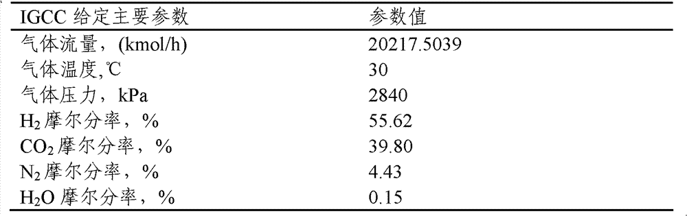
[0039] Contains CO 2 The mixed gas, temperature 30 ℃, pressure 2800KPa, composition (mol fraction) as shown in table 4:

[0040] Table 4 Feed gas flow rate and composition

[0041]

[0042] CO removal with absorber overhead 2 After heat exchange, the purified gas is lowered to 24°C and enters the absorption tower from the lower part, and the diethyl carbonate from the absorbent storage tank at 25°C exchanges heat with the desorbed circulating absorbent lean liquid and enters the absorption tower from the upper part after heat exchange to 5°C. The agent flow rate is 44919.15kmol / h. The two phases are in countercurrent contact in the column and absorption mass transfer occurs. The temperature at the top of the absorption tower is 19°C and the pressure is 2800KPa; the temperature at the bottom of the tower is 24°C and the pressure is 2840KPa. CO removal 2 After heat exchange between the purified gas and the feed gas, the temperature is lowered to 24°C and discharged from ...

Embodiment 3

[0052] Contains CO 2 The mixed gas, temperature 30 ℃, pressure 2800KPa, composition (mol fraction) as shown in Table 7:

[0053] Table 7 Feed gas flow rate and composition

[0054]

[0055] CO removal with absorber overhead 2 After heat exchange, the purified gas drops to 24°C and enters the absorption tower from the lower part. The diethyl carbonate from the absorbent storage tank at 25°C exchanges heat with the desorbed circulating absorbent poor liquid and enters the absorption tower from the upper part after heat exchange to 7°C. The agent flow rate is 33737.37kmol / h. The two phases of gas and liquid are in countercurrent contact in the tower and absorption and mass transfer occur. The temperature at the top of the absorption tower is 19.0°C and the pressure is 2800KPa; the temperature at the bottom of the tower is 28°C and the pressure is 2840KPa. CO removal 2 After heat exchange between the purified gas and the feed gas, the temperature is lowered to 25°C and dis...


PUM


Abstract

The invention provides a decarburization method adopting diethyl carbonate as an absorbent. The method comprises the following steps: firstly enabling raw material gas containing CO2 to pass through the diethyl carbonate for absorption and decarburization, then enabling absorbent pregnant solution after absorbing the CO2 to pass through two-stage decompression desorption, and enabling the CO2 gasgenerated by desorption to pass through compression, cooling and recovery of a solvent, namely the diethyl carbonate, entrained in the gas phase, and then be discharged out of a boundary region. Compared with the propene carbonate method which is maturely applied in the industry at present, the developed diethyl carbonate decarburization process can reduce the energy consumption by above 30%; compared with the polyethylene glycol dimethyl ether method, the price of the solvent is lower, the polymerization loss can be reduced by above 50%; compared with the low-temperature methanol washing process, the operation temperature is more moderate, and equipment investment can be reduced by more than 30%. The CO2 removal efficiency can be more than 85%-95%.

Description

technical field [0001] The invention relates to a method for absorbing and removing CO from medium and high pressure gas mixtures, including synthesis gas, shift gas and IGCC gas 2 The technology belongs to the technical field of chemical engineering. Background technique [0002] Global warming has become an undisputed fact. Greenhouse gas CO 2 emissions are a major contributor to climate warming. How to get from rich CO 2 Capture and separation of CO in the gas mixture of synthetic gas, shift gas and IGCC gas 2 extremely important. [0003] According to different application occasions and the pressure of feed gas, the decarburization method can be divided into dry method and wet method. Dry methods include adsorption methods and membrane methods, and are generally applicable to CO 2 Where the concentration is low; the wet method can be divided into chemical absorption method and physical absorption method, and the chemical absorption method is mostly used in occasio...

Claims


Application Information

Patent Timeline
Patent Type & Authority Patents(China)
IPC IPC(8): B01D53/14
CPCY02C10/06Y02A50/20Y02C20/40
Inventor 费维扬汤志刚陈健骆广生桂霞李铁枝郭栋
Owner TSINGHUA UNIV
Why Eureka
Try Eureka