
High-overload high-temperature-resistant oil-immersed transformer

An oil-immersed transformer, high temperature resistant technology, applied in the field of transformers, can solve problems such as ground short circuit, economic loss, inter-turn short circuit, etc., and achieve the effect of reducing the width of the oil tank, compact overall structure, and reducing the height of the oil tank

Inactive Publication Date: 2016-10-05
江西变电设备有限公司
View PDF20 Cites 6 Cited by
  • Summary
  • Abstract
  • Description
  • Claims
  • Application Information

AI Technical Summary

Problems solved by technology

Although the flash point of insulating oil is generally higher than 145°C, insulating oil is easily decomposed at high temperature and burns when exposed to an open flame
If the transformer is overloaded for a long time, the coil will heat up and the insulation will gradually age, which will easily cause a short circuit between turns, short circuit between phases or short circuit to ground.
When a short circuit occurs, the flammable insulating material and insulating oil in the transformer will be decomposed by the action of high temperature and electric arc, expand and gasify, which will cause the internal pressure of the transformer to increase sharply, and even cause the transformer to explode in serious cases, which will not only affect the normal power supply Dispatch, and will cause significant economic losses and casualties

Method used


Image

  • High-overload high-temperature-resistant oil-immersed transformer
  • High-overload high-temperature-resistant oil-immersed transformer
  • High-overload high-temperature-resistant oil-immersed transformer

Examples


Embodiment Construction

[0041] The following will clearly and completely describe the technical solutions in the embodiments of the present invention with reference to the accompanying drawings in the embodiments of the present invention. Obviously, the described embodiments are only some, not all, embodiments of the present invention. Based on the embodiments of the present invention, all other embodiments obtained by persons of ordinary skill in the art without making creative efforts belong to the protection scope of the present invention.

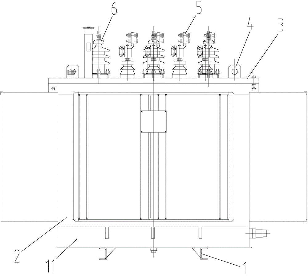
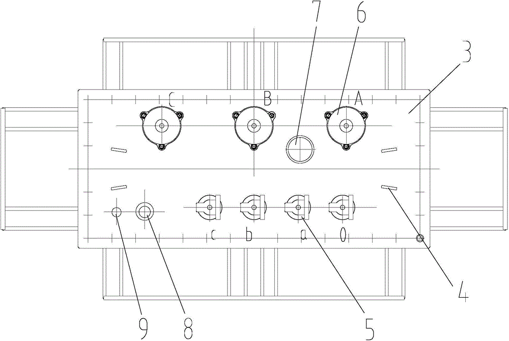
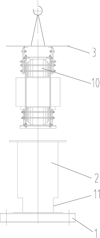
[0042] Such as figure 1 , figure 2 and image 3 As shown, the high-overload and high-temperature-resistant oil-immersed transformer in this embodiment includes an underframe 1, and an oil tank 2 is arranged on the underframe 1, and the inner and outer surfaces of the oil tank 2 are sprayed with organic high-temperature-resistant paint, where the organic high-temperature-resistant paint is made of fat family polyurethane enamel. In this embodiment, the oil ...


PUM


Abstract

The invention provides a high-overload high-temperature-resistant oil-immersed transformer which comprises an underframe and an oil tank. A tank cover is arranged at an upper end opening of the oil tank, a rubber strip is arranged between the upper end opening of the oil tank and the tank cover, a transformer core is arranged in the oil tank, and the oil tank is filled with 110-kv high-temperature-resistant insulation oil. Lifting plates, low-voltage sleeves, high-voltage sleeves, a tap switch, an oil level indicator and a thermometer seat are arranged on the upward face of the tank cover, the lifting plates are symmetrically distributed at the four corners of the tank cover, the low-voltage sleeves are evenly distributed on one side of the tank cover, and the high-voltage sleeves are evenly distributed on the other side of the tank cover. The transformer core comprises an iron core, a low-voltage coil is wound around the outside of the iron core, a high-voltage coil is wound around the outside of the low-voltage coil, the high-voltage coil passes through the tap switch to be connected with the high-voltage sleeves, and the low-voltage coil is connected with the low-voltage sleeves. Turn insulation of the high-voltage coil and the low-voltage coil is NOMEX insulation paper; the front side wall and the rear side wall of the lower end of the oil tank are concave inwards to form bottom grooves. The high-overload high-temperature-resistant oil-immersed transformer is small in size, compact in structure, long in service life and resistant to high temperature.

Description

technical field [0001] The invention relates to the technical field of transformers, in particular to a high overload and high temperature resistant oil-immersed transformer. Background technique [0002] Oil-immersed transformers are suitable for power systems, industrial and mining enterprises, transportation, post and telecommunications departments, scientific research units, etc., to conduct dielectric strength tests on various high-voltage electrical equipment, electrical components, and insulating materials under power frequency or DC high voltage. Oil-immersed transformers rely on oil as the cooling medium, such as oil-immersed self-cooling, oil-immersed air-cooled, oil-immersed water-cooled and forced oil circulation. The role of oil is insulation, heat dissipation, and arc elimination. Generally, the main transformer of the step-up station is oil-immersed, with a transformation ratio of 20KV / 500KV, or 20KV / 220KV. Generally, the factory transformer used to drive its...

Claims


Application Information

Patent Timeline
IPC IPC(8): H01F27/14H01F27/40H01F27/30H01F27/32H01F27/26
Inventor 王玮陈益平周晨光章小英赖文华
Owner 江西变电设备有限公司
Learn More