Double-main-shaft numerical control lathe

A CNC lathe and double-spindle technology, applied in the field of lathe machinery, can solve the problems of unfavorable heat dissipation, inconvenient transportation, uneven force on both sides, etc., improve machining accuracy and stability, compact and reasonable overall structure, and reduce floor space Effect

Inactive Publication Date: 2016-10-12
新昌县三特自动化科技有限公司
View PDF9 Cites 3 Cited by
  • Summary
  • Abstract
  • Description
  • Claims
  • Application Information

AI Technical Summary

Problems solved by technology

This processing method has the following disadvantages: First, the two lathes must be placed side by side, which actually occupies a large area; secondly, the manipulator is installed separately outside the machine tool, and the manipulator moves from one lathe to the other with the workpiece. The stroke is longer and the processing efficiency is lower
Generally, only one headstock and one saddle are installed on the bed of existing CNC lathes, which are not symmetrically arranged. The force on both sides is uneven, easy to deform, and it is very easy to generate vibration during work, which will not only affect the quality of the workpiece. accuracy, and the life of the lathe itself will also be affected
[0004] There are saddle guide rails for installing saddles on the bed. The existing saddle guide rails are all set at an angle of 45 degrees to the horizontal plane. The casting is difficult, the processing is slow, and the cost is high, and it is easy to deform during use.
In addition, the water tank and hydraulic oil tank of existing CNC lathes are usually arranged outside the bed, which not only increases the area of ​​the lathe, is inconvenient to transport, but also is not conducive to heat dissipation
[0005] In addition, the existing saddle includes a saddle slider installation surface installed on the bed and a guide rail installation surface for installing the upper slide. The saddle slider installation surface and the guide rail installation surface are parallel to each other, and the saddle slider installation surface and The installation surfaces of the guide rails are connected by an integrated rectangular support frame. In order to ensure rigidity, the consumables of this rectangular support frame are often more
In order to meet the needs of work, the installation surface of the guide rail must be set at 45° to the horizontal plane during use, which leads to the installation surface of the saddle slider also at 45°, that is, the upper surface of the bed must also be set at 45°, and this 45° The bed is more difficult to cast, and the processing cost is higher
In addition, the saddle itself with this structure is more difficult to process, and there are many consumables, and the manufacturing cost is relatively high

Method used


Image

  • Double-main-shaft numerical control lathe
  • Double-main-shaft numerical control lathe
  • Double-main-shaft numerical control lathe

Examples


Embodiment Construction

[0022] Specific embodiments of the present invention will be described below with reference to the accompanying drawings.

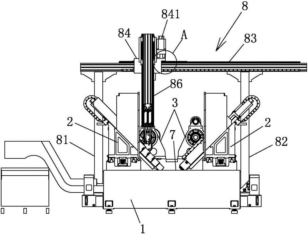
[0023] refer to figure 1 , a dual-spindle CNC lathe, comprising a bed 1, two symmetrical left and right saddles 2 and two symmetrical left and right spindle boxes 3, the left and right spindle boxes 3 and the left and right saddles 2 are all installed On the bed 1, the left headstock 3 corresponds to the left saddle 2, and the right headstock 3 corresponds to the right saddle 2. The numerically controlled lathe also includes a truss manipulator 8, which is a two-degree-of-freedom manipulator.

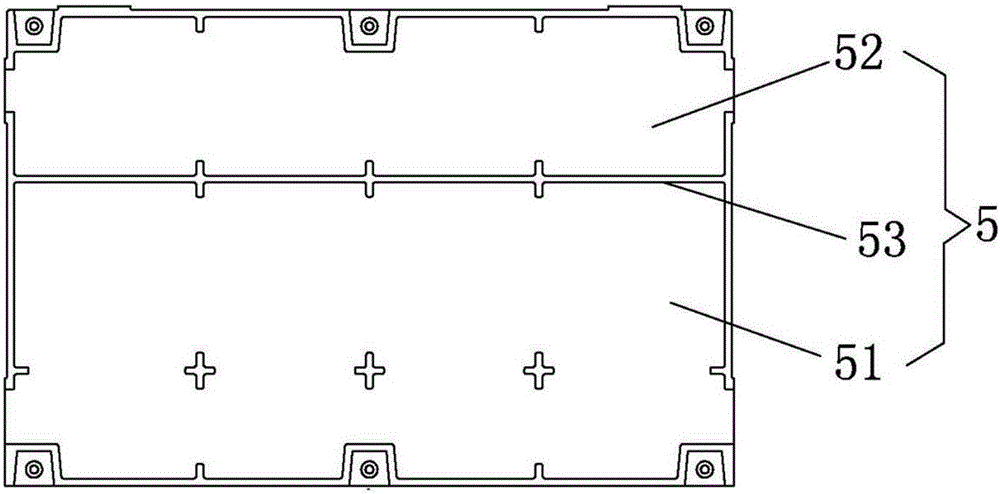
[0024] Also refer to image 3 , the X-axis guide rail 31 is equipped with a rack 311, the X slider 32 is equipped with a servo motor 61 for use, the front end of the servo motor 61 is equipped with a gear 611, the gear 611 moves on the rack 311, and Drive the X slider 32 to move horizontally on the X-axis guide rail 31; a rack (not shown in the figure due to the...


PUM


Abstract

The invention discloses a double-main-shaft numerical control lathe. The double-main-shaft numerical control lathe comprises a body, saddles, a two-degree-of-freedom truss manipulator and main shaft boxes; left and right two symmetric saddles are arranged on the body; left and right two symmetric main shaft boxes are arranged on the body; the left saddle is corresponding to the left main shaft box in position; and the right main shaft box is corresponding to the right saddle in position. The two main shaft boxes and the two saddles are symmetrically mounted on the body; the double-main-shaft numerical control lathe is matched with a truss manipulator for independently finishing machining of machined parts without needing matched use of two lathes, so that the floor area is reduced; and in addition, the numerical control lathe adopts symmetric layout, is uniform in stress during machining, reduces the deformation, and improves the machining precision and the stability. In addition, the truss manipulator is shorter in travel during working, so that the working efficiency is higher, and the market prospect is broad.

Description

technical field [0001] The invention relates to the field of lathe machinery, in particular to a double-spindle numerical control lathe. Background technique [0002] Generally, only one headstock and one saddle are installed in the cabinet of existing CNC lathes. One lathe can only complete half of the processing of the workpiece, and often requires the cooperation of two lathes to complete the complete processing of one workpiece. In actual production, two lathes are usually arranged side by side, and the semi-finished product is processed on one machine tool first, and then the semi-finished product is grabbed by the manipulator to another lathe to process the finished product. This processing method has the following disadvantages: First, the two lathes must be placed side by side, which actually occupies a large area; secondly, the manipulator is installed separately outside the machine tool, and the manipulator moves from one lathe to the other with the workpiece. Its...

Claims


Application Information

Patent Timeline
Patent Type & Authority Applications(China)
IPC IPC(8): B23B19/02B23B21/00B23B15/00B23Q1/00
CPCB23Q1/70B23Q1/0009B23Q1/25B23Q7/046
Inventor 梁志祥
Owner 新昌县三特自动化科技有限公司
Why Eureka
Try Eureka