Slag trough structure and construction method for same

A construction method and slag ditch technology, applied in infrastructure engineering, excavation, construction, etc., can solve problems such as drainage without specific implementation plans, and achieve the effects of saving manpower, preventing water seepage, and ensuring construction quality

Inactive Publication Date: 2016-10-12
马钢集团设计研究院有限责任公司
View PDF7 Cites 4 Cited by
  • Summary
  • Abstract
  • Description
  • Claims
  • Application Information

AI Technical Summary

Problems solved by technology

Its shortcoming is that although this patent can speed up the construction progress, it does not give a specific implementation plan for the drainage of the construction process. If you want to speed up the construction progress and simplify the construction process, there are still certain difficulties

Method used


Image

  • Slag trough structure and construction method for same
  • Slag trough structure and construction method for same
  • Slag trough structure and construction method for same

Examples


Embodiment 1

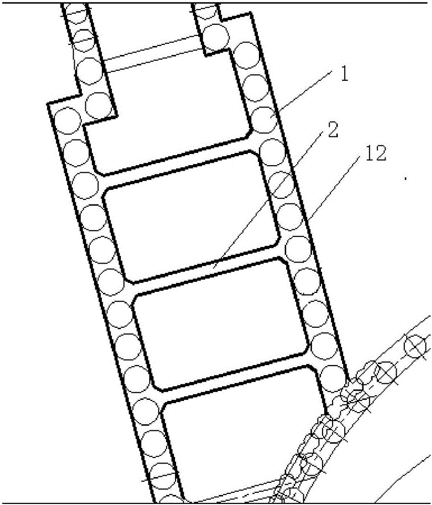
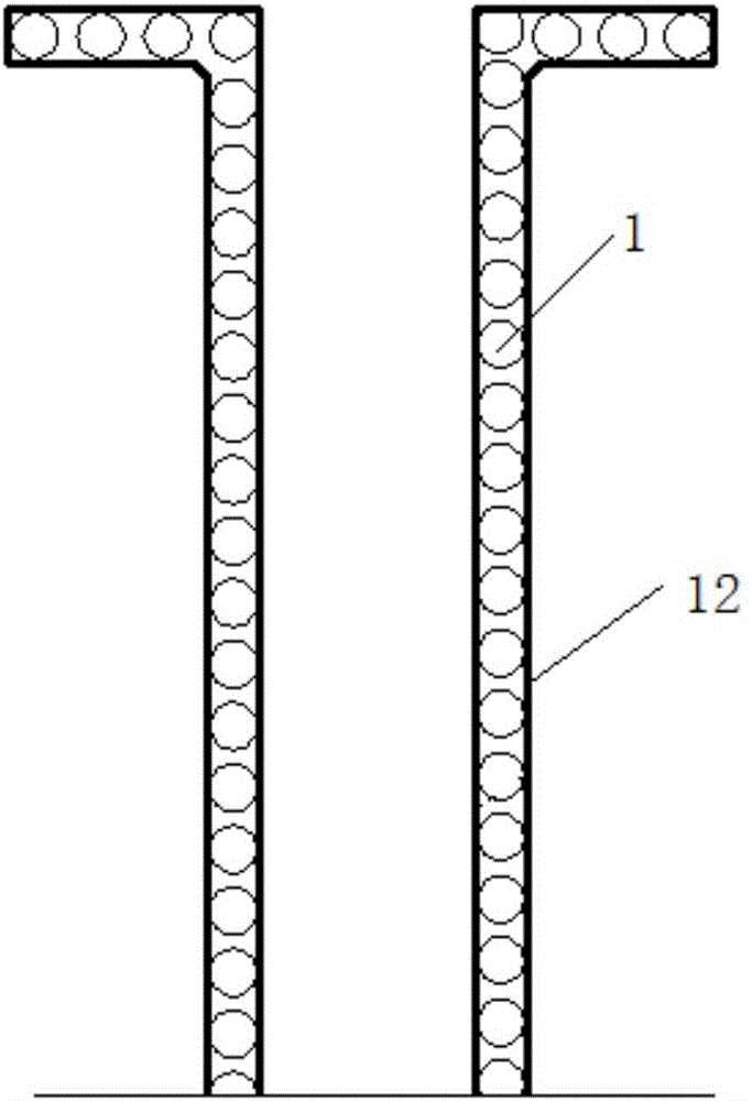
[0049] Combine Figure 1-7 , A slag ditch structure includes a supporting beam 2 and a slag ditch wall 12. A supporting pile 1 is provided on the outside of the slag ditch wall 12, and a supporting beam 2 is arranged between the supporting piles 1; the supporting pile 1 includes a water stop Pile and water-stop curtain pile 5, the water-stop curtain pile 5 is set between two adjacent water-stop piles; supporting pile 1 is a bored pile, use a drill to drill the hole, put the steel cage down into the hole, and cast cement. During the construction of supporting pile 1, strictly control the pile position, pile top and bottom elevation, mud specific gravity, and underwater concrete quality to ensure the construction quality of supporting pile 1.

[0050] The number of water-stopping piles is more than two rows, which is to strengthen the water-stopping effect, and the water-stopping piles can also play a role in resisting the lateral pressure of the soil; the water-stopping piles are...

Embodiment 2

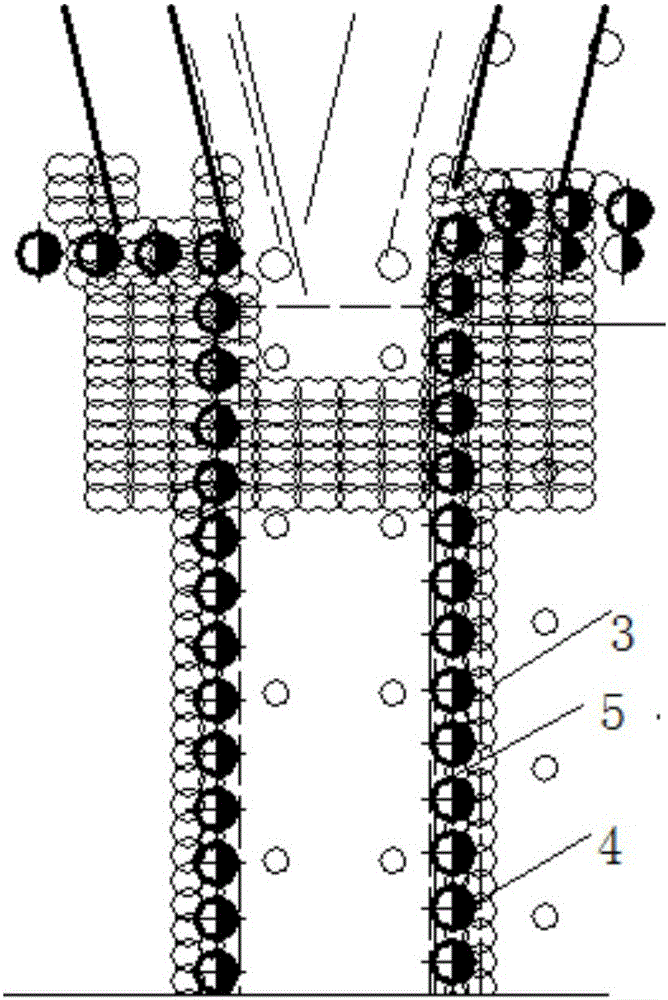
[0063] Similar to Example 1, combined Figure 1-7 In this embodiment, two rows of water stop piles are used, and the construction sequence is to pour the second row of water stop piles 4 first, then pour the first row of water stop piles 3, and the second row of water stop piles 4 using bored pile construction , The bored pile uses a rotary drilling machine to form the hole, the underwater concrete is poured in the construction process, and the hole jumps to form the hole; the thickness of the steel protection layer of the bored pile is 50mm, and the vertical deviation of the bored pile is less than or equal to 1 / 200; the thickness of the pile tip sediment is less than or equal to 50mm.

[0064] In the production of water-stop curtain piles, the diameter of the high-pressure jet-grouting pile is 700mm. The high-pressure jet-grouting pile needs to penetrate the sand and silt soil layer. The length of overlap between each water-stop pile and each row of water-stop piles Both are 1...

Embodiment 3

[0067] Similar to Example 2, Image 6 The steel cage 11 in the steel includes welded reinforcement hoop 15, spiral stirrup 14 and main reinforcement 13, such as Figure 7 Shown. Reinforcing steel cage 11 is required to be integrally manufactured and hoisted; the steel joints shall be flash butt welding or mechanical connection joints, and lap joints shall not be used; the thickness of the protective layer of the steel reinforcement of the supporting pile 1 is 50mm, and the second row of water-stop pile 4 is poured cement Use C30 grade; C15 grade for cushion.

[0068] Real-time example 4

[0069] A construction method of slag trench structure, the steps are:

[0070] A. Design the overall plan, and calculate the number and size of water stop piles according to the size of the slag trench;

[0071] B. Excavate the foundation pit in the selected area; the depth of the foundation pit is 3m; it can reduce the length of the second row of water stop piles and reduce the construction cost; s...


PUM


Abstract

The invention discloses a slag ditch structure and a construction method thereof, belonging to the field of foundation pit construction. It includes support beams and slag ditch walls. Support piles are arranged outside the slag ditch walls, and support beams are arranged between the support piles. The supporting piles include water-stop piles and water-stop curtain piles, and the water-stop curtain piles are arranged between two adjacent water-stop piles. The supporting piles are bored cast-in-place piles, which are drilled with a drilling rig, then the steel cage is lowered into the hole, and concrete is poured. During the construction of the supporting piles, the pile position, the elevation of the top and bottom of the pile, the specific gravity of the mud, and the quality of the underwater concrete are strictly controlled. The number of water-stop piles is set to more than two rows, which is to strengthen the water-stop effect, and the water-stop piles can also play a role in resisting the lateral pressure of the soil. It can prevent water from entering the slag ditch, and can also bear the side pressure of the soil. The high-pressure rotating nozzle sprays the cement slurry into the soil layer and mixes with the soil to form a continuous lapped cement reinforcement. The construction occupies less land, has less vibration and less noise. Low.

Description

Technical field [0001] The invention relates to the field of foundation pit construction, in particular to a slag trench structure and a construction method thereof. Background technique [0002] The slag ditch foundation pit is located in the middle of the main rolling line foundation pit. It is a long and narrow pit in the pit with a length of about 160m and a width of about 4m. It is 3-7m deep relative to the main rolling line foundation pit. Its support method is related to the overall foundation pit. Safety is also related to the construction progress of the hot rolling equipment foundation. Supporting methods such as single-row cast-in-place piles + crown beams + 1-2 steel internal braces, steel sheet piles + 1-2 steel internal braces, and reinforced concrete gravity retaining walls are usually used. [0003] The main foundation pit has been excavated during the excavation of the slag ditch foundation pit. If the support method with internal support is used, a large crane st...

Claims


Application Information

Patent Timeline
Patent Type & Authority Applications(China)
IPC IPC(8): E02D17/02E02D17/06
CPCE02D17/02E02D17/06
Inventor 陈瑛
Owner 马钢集团设计研究院有限责任公司
Why Eureka
Try Eureka