Structure for constructing underwater foundation and mounting method thereof

A technology for underwater foundations and pile foundations, which is applied in infrastructure engineering, architecture, sustainable buildings, etc., and can solve the problems of single pile foundation diameter, wall thickness, penetration depth increase, complex structure and construction technology, and difficulties in offshore piling construction and other problems to achieve the effect of avoiding foundation fracture, good horizontal bearing capacity and convenient construction

Inactive Publication Date: 2018-02-23
CHINA METALLURGICAL CONSTR HIGH TECH ENG TECH CO LTD
View PDF4 Cites 2 Cited by
  • Summary
  • Abstract
  • Description
  • Claims
  • Application Information

AI Technical Summary

Problems solved by technology

However, due to the weaknesses of the single pile foundation such as poor anti-overturning ability and large horizontal displacement, as the single unit capacity of offshore wind turbines increases to 3MW, 5MW or more, the diameter, wall thickness and penetration depth of the single pile foundation will inevitably increase sharply. Large, resulting in difficulties in offshore piling construction and a substantial increase in construction costs
[0003] Three-pile tripods, multi-pile jackets, and barrel foundations can effectively disperse loads and improve overturning resistance through different methods, but their structures and construction processes are complex, and they have high requirements for sea conditions, resulting in long construction periods and high construction costs.
In addition, this method is not conducive to construction in ecologically sensitive areas, and large decibel noise and high-frequency sound emissions are caused by this method

Method used


Image

  • Structure for constructing underwater foundation and mounting method thereof
  • Structure for constructing underwater foundation and mounting method thereof
  • Structure for constructing underwater foundation and mounting method thereof

Examples


Embodiment 1

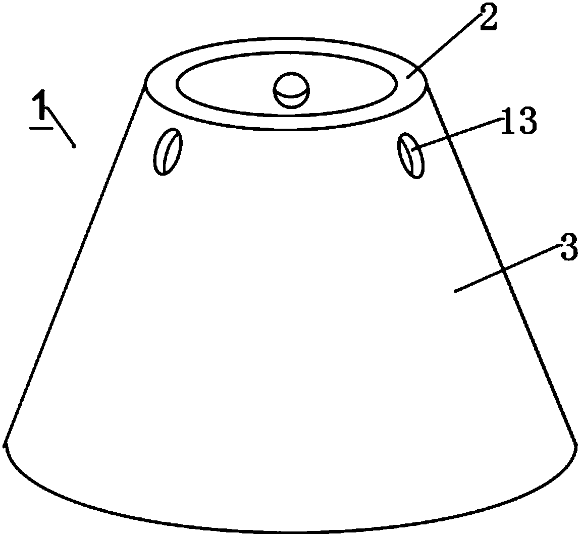
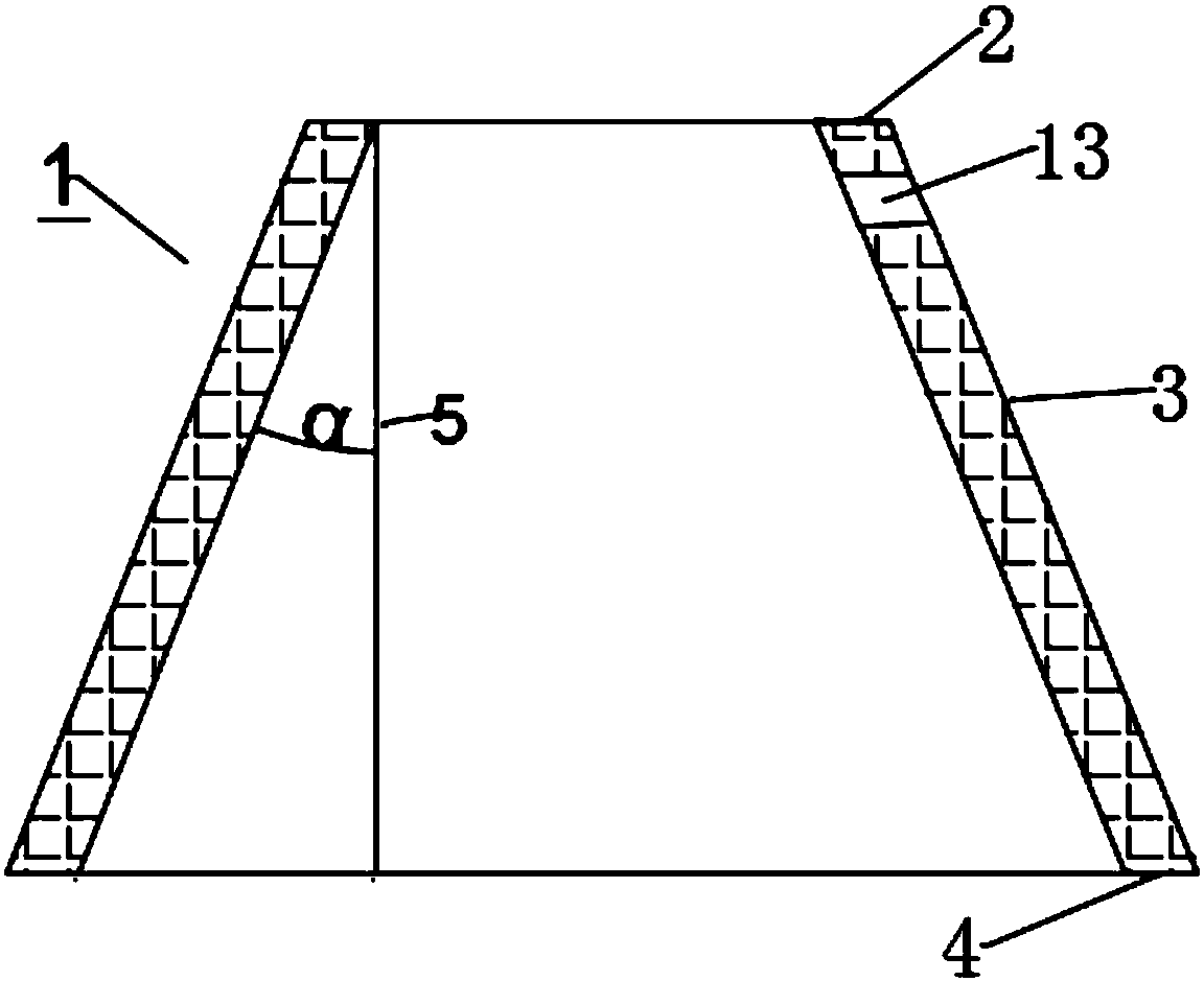
[0038] Such as Figure 1-2 As shown, the main body of the basic structure of the present invention is a hollow circular frustum structure. The hollow circular frustum structure 1 is a concrete structure with an outer diameter of the upper bottom surface 2 of 3m, an outer diameter of the lower bottom surface 4 of 21m, a wall thickness of the side surface 3 of 600mm, and a height 5 of 15m. α is 30°. When laying piles in the water, the foundation structure 1 is erected, the lower bottom surface 4 is inserted under the mud surface 8, and the upper bottom surface 2 is exposed to the water surface 7 . The outer diameters of the upper and lower bottom surfaces of the pile foundation 1 are calculated and determined depending on different soil properties and bearing capacity. The circular frustum structure of the present invention makes the side 3 form an angle with the water flow, so the impact force of the water flow on the front of the side is dispersed due to the angle, thereby pr...

Embodiment 2

[0046] Such as Figure 1-2 As shown, the main body of the basic structure of the present invention is a hollow circular frustum structure. The hollow circular frustum structure 1 is a steel circular frustum structure with an outer diameter of the upper bottom surface 2 of 10m, an outer diameter of the lower bottom surface 4 of 26m, a wall thickness of 60mm, and a height of 30m. The outer steel surfaces are all waterproofed, and α is 15°. When laying piles at sea, the foundation structure 1 is erected, the lower end is inserted into the mud surface 8, and the upper end is exposed to the water surface 7 . The outer diameters of the upper and lower bottom surfaces of the pile foundation 1 are calculated and determined depending on different soil properties and bearing capacity. The circular frustum structure of the present invention makes the side 3 form an angle with the water flow, so the impact force of the water flow on the front of the side is dispersed due to the angle, th...

Embodiment 3

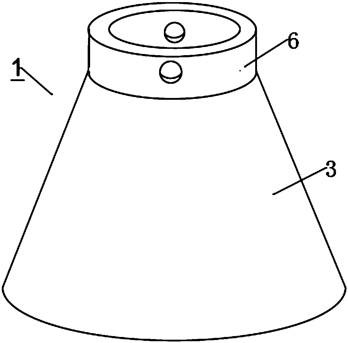
[0053] Such as Figure 3-4 As shown, the main body of the basic structure of the present invention is a hollow circular frustum structure. The hollow circular platform structure of the pile foundation 1 is a concrete structure with an outer diameter of the upper bottom surface 2 of 5m, an outer diameter of the lower bottom surface 4 of 20m, a wall thickness of 600mm, and a height 5 of 30m, and α is 20°. The upper bottom surface 2 of the pile foundation 1 is provided with a transition section 6, the transition section 6 is a cylindrical structure, the bottom of the transition section 6 is welded to the upper bottom surface 2 of the pile foundation 1, the inner and outer diameters of the transition section 6 and the upper The inner and outer diameters of the bottom surface 2 are consistent, and the height of the transition section 6 is 1M. The transition section 6 is provided with more than two hanging points 13 . When laying piles in the water, the pile foundation 1 is erected...


PUM


Abstract

The invention discloses an underwater building foundation structure which is a hollow round-table-shaped structure. The structure is characterized in that the advantages, such as clear force-bearing state, high soil applicability, convenient construction and high horizontal bearing capacity of the round table structure, of a single-pile foundation, are fully utilized; the overall rigidity, the horizontal load resistance, the vertical load resistance and the anti-bending capacity of the structure are greatly improved; the bending load caused by wind turbine load to the foundation can be effectively reduced; the horizontal displacement of a wind-powered generations structure is reduced; the sedimentation value is decreased. Therefore, the pile length, the pile diameter, the wall thickness and the extending depth of the pile foundation can be reduced; the material cost is greatly decreased; the construction technology is simple. The structure also has the characteristics of being resistant to corrosion, and long service life in water. The invention also discloses a method for mounting the underwater building foundation structure. The underwater building foundation structure can be mounted in an area with complex underwater condition through the method.

Description

technical field [0001] The invention relates to a basic structure in the field of underwater buildings, in particular to a method for building an underwater basic structure and its installation. Background technique [0002] In the construction of foundation-supported buildings on submerged soil, such foundations are constructed in different ways, wherein the use of single piles, ie, single piles, is already implemented in the one-piece foundation. The monopile foundation structure is a common form of underwater structure foundation, especially in the field of offshore wind power, and it is most widely used in European offshore fields. Its structure is simple and its force mechanism is clear, and it is economical to use for wind turbines below 1.5MW. However, due to the weaknesses of the single pile foundation such as poor anti-overturning ability and large horizontal displacement, as the single unit capacity of offshore wind turbines increases to 3MW, 5MW or more, the diame...

Claims


Application Information

Patent Timeline
Patent Type & Authority Applications(China)
IPC IPC(8): E02D27/42E02D27/24E02D5/48E02D7/00E02D7/28E02D5/50
CPCY02B10/30E02D27/425E02D5/48E02D5/50E02D7/00E02D7/28E02D27/24
Inventor 李建营潘辉田金成苏兴刘海峰张广涛韩永生
Owner CHINA METALLURGICAL CONSTR HIGH TECH ENG TECH CO LTD
Why Eureka
Try Eureka