Compressed hydrogen storage and charging system of hydrogen refueling station

A technology of gas filling system and hydrogen refueling station, which is applied in gas/liquid distribution and storage, container filling method, equipment loaded into pressure container, etc.

Inactive Publication Date: 2016-10-12
CHINA PETROLEUM & CHEM CORP +1
View PDF7 Cites 21 Cited by
  • Summary
  • Abstract
  • Description
  • Claims
  • Application Information

AI Technical Summary

Problems solved by technology

When the gas consumption is at its peak, there is usually a phenomenon that the gas volume in the gas storage cylinder group is insufficient, and it is difficult to fill the on-board gas storage cylinder of the hydrogen fuel vehicle in a short period of time.

Method used


Image

  • Compressed hydrogen storage and charging system of hydrogen refueling station

Examples


Embodiment 1

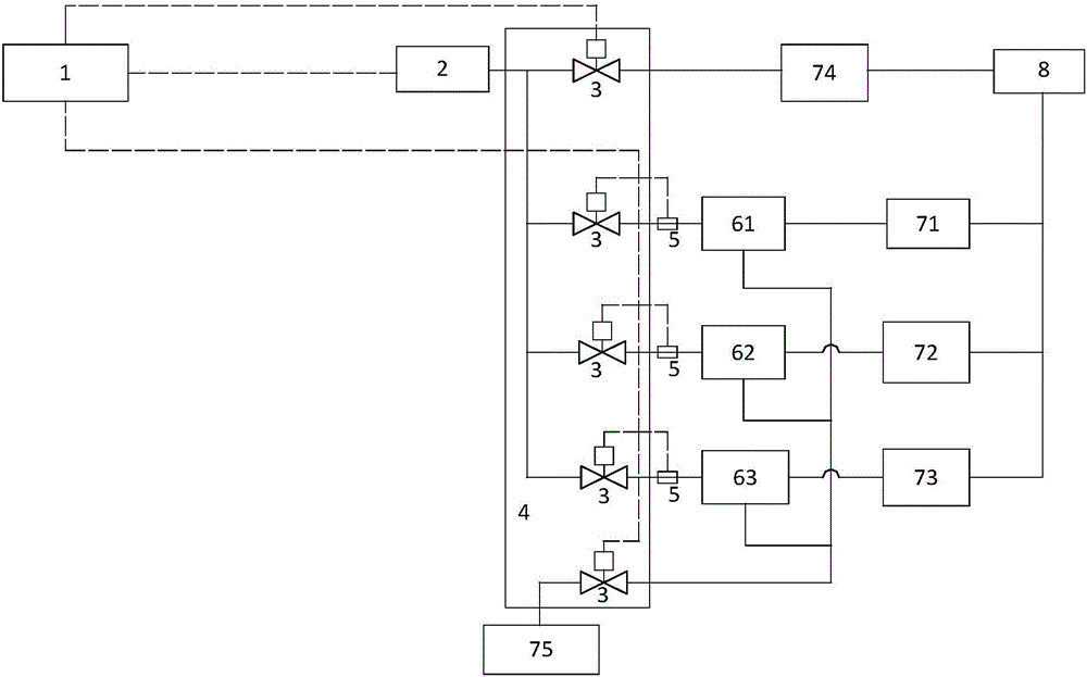
[0021] Such as figure 1 As shown, this embodiment provides a hydrogen compression gas storage and inflation system for a hydrogen refueling station, including a compressor 2, a gas control valve 3, a pressure distribution adjustment box 4, a high-pressure gas storage cylinder 61, a medium-pressure gas storage cylinder 62, a low-pressure gas storage cylinder The gas storage cylinder 63, the pressure sensor 5, the data controller 1, and the compressor 2 are respectively connected to the high-pressure gas storage cylinder 61, the medium-pressure gas storage cylinder 62, the low-pressure gas storage cylinder 63, and the direct charging pipeline 74 through the pneumatic valve 3 pipelines. The gas storage bottle 61, the medium pressure gas storage bottle 62 and the low pressure gas storage bottle 63 are respectively connected with the high pressure gas filling pipeline 71, the medium pressure gas filling pipeline 72 and the low pressure gas filling pipeline 73 through pipelines, and ...

Embodiment 2

[0025] The difference between this embodiment and Embodiment 1 is that the data controller 1 is a programmable logic controller, which has high reliability and strong anti-interference ability, and can stably and efficiently control the hydrogen compression gas storage system. Storage operation. The data controller 1 can also be an intelligent mobile terminal, such as a smart phone. The data controller 1 is connected to the pneumatic valve 3, the pressure sensor 5 and the compressor 2 via Bluetooth signals, and the data controller 1 controls the opening of the pneumatic valve 3 and the compressor 2. and closed, the data controller 1 monitors the pressure of each gas storage bottle through the pressure sensor 5, and realizes the intelligent control of hydrogen compression storage and gas filling in the hydrogen refueling station. In addition, the signal cable connection between the pneumatic valve 3, the pressure sensor 5, and the compressor 2 and the data controller 1 is omitt...


PUM


Abstract

The invention proposes a compressed hydrogen storage and charging system of a hydrogen refueling station. A compressor is respectively connected with a high-pressure gas storage cylinder, a medium-pressure gas storage cylinder, a low-pressure gas storage cylinder and a direct charging pipeline by control valve pipelines; the high-pressure gas storage cylinder, the medium-pressure gas storage cylinder and the low-pressure gas storage cylinder are respectively connected with a high-pressure gas charging pipeline, a medium-pressure gas charging pipeline and a low-pressure gas charging pipeline by pipelines, and are all connected with a release pipeline by pipelines; a gas inlet side pipeline of the release pipeline is connected with a control valve; pipelines on gas intake sides of the high-pressure gas storage cylinder, the medium-pressure gas storage cylinder and the low-pressure gas storage cylinder are all connected with pressure sensors; and a data controller is in signal connection with the pressure sensors and the compressor. The system has the following beneficial effects: the system not only can charge vehicle-mounted gas storage cylinders of hydrogen fuel vehicles through the gas storage cylinder set, but also can directly charge the vehicle-mounted gas storage cylinders of the hydrogen fuel vehicles so as to realize intelligent control of compressed hydrogen storage and charging of the hydrogen refueling station.

Description

technical field [0001] The invention relates to the technical field of hydrogen gas storage in a hydrogen refueling station, in particular to a hydrogen compression gas storage and gas charging system in a hydrogen refueling station. Background technique [0002] The hydrogen fuel cell working process of hydrogen fuel vehicles can achieve zero emissions, and there is no hydrogen leakage problem. Compared with electric vehicle lithium batteries, the performance is more stable and safe. The technology of the vehicle-mounted hydrogen high-pressure gas storage tank is also mature and has high safety. The hydrogen refueling time of hydrogen fuel vehicles is equivalent to that of gasoline and diesel vehicles, and the cruising range of hydrogen fuel vehicles can reach more than 500 kilometers, which is about twice that of electric vehicles. The hydrogen refueling of hydrogen fuel vehicles needs to be carried out in hydrogen refueling stations, and the country needs to gradually es...

Claims


Application Information

Patent Timeline
Patent Type & Authority Applications(China)
IPC IPC(8): F17C5/06F17C13/02
CPCF17C5/06F17C13/025F17C2227/04F17C2250/032F17C2250/043F17C2250/0626Y02E60/32
Inventor 周日峰许光张健中赵雯晴
Owner CHINA PETROLEUM & CHEM CORP
Why Eureka
Try Eureka