Boiler system adopting electromagnetic induction type heating mode and implementation method thereof

A realization method, an inductive technology, applied in the field of high-pressure boilers, can solve the problems of low energy conversion rate, slow heating speed, high manufacturing cost, etc., and achieve the effects of high safety, fast heating speed and low cost

Inactive Publication Date: 2016-10-12
东阳市东德环保设备有限公司
View PDF7 Cites 2 Cited by
  • Summary
  • Abstract
  • Description
  • Claims
  • Application Information

AI Technical Summary

Problems solved by technology

[0004] (1) Larger environmental pollution;
[0005] (2), the energy conversion rate is low;
[0006] (3), the heating rate is slow;
[0007] (4), relatively low security;
[0008] (5), complex structure, difficult processing, high manufacturing cost

Method used


Image

  • Boiler system adopting electromagnetic induction type heating mode and implementation method thereof
  • Boiler system adopting electromagnetic induction type heating mode and implementation method thereof
  • Boiler system adopting electromagnetic induction type heating mode and implementation method thereof

Examples


Embodiment 1

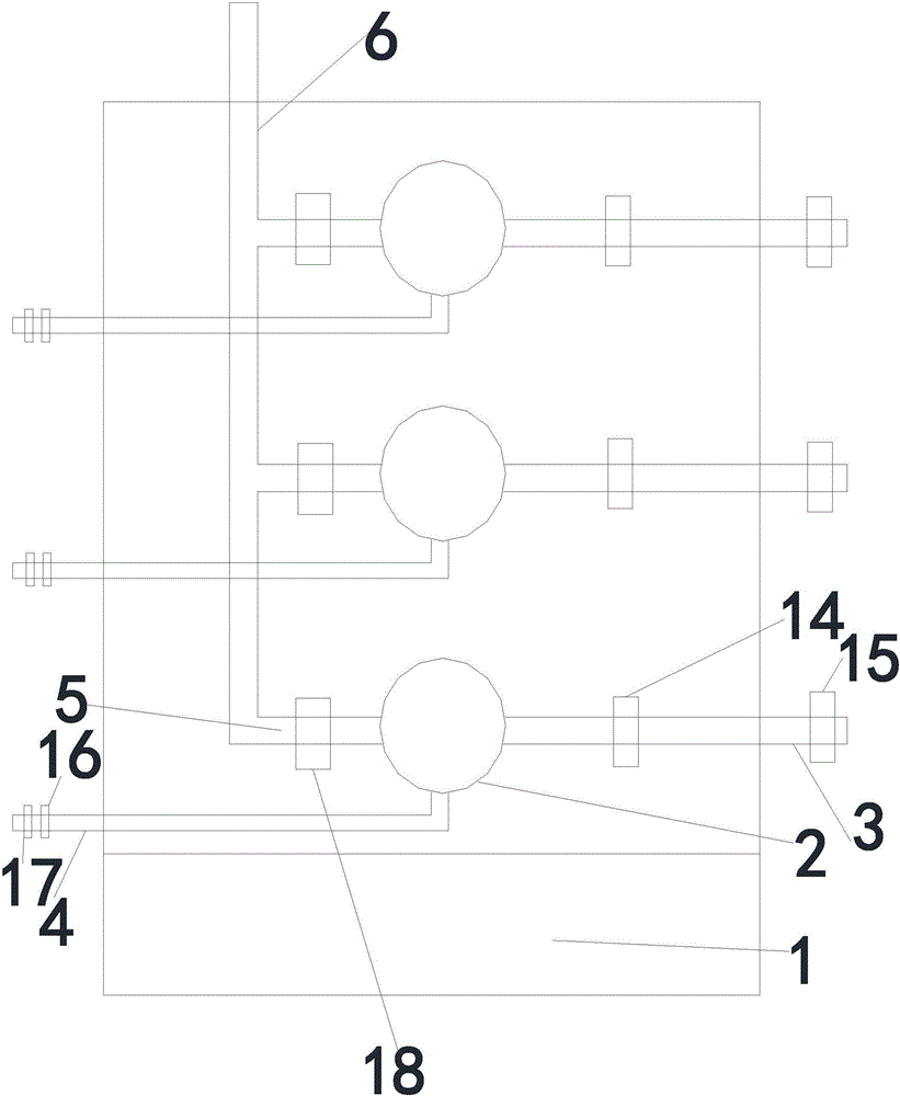
[0043] Such as Figure 1~2 As shown, an electromagnetic induction heating boiler system includes a control room, a controller is arranged in the control room, and several electromagnetic induction heating boilers are arranged in the heating room, and each boiler is equipped with a water inlet pipe, a sewage pipe and an air outlet pipe. Sub-pipes, the outlet sub-pipes are collected on the outlet main pipe.

[0044] The boiler in this embodiment includes a furnace cylinder, an insulation layer is arranged inside the furnace cylinder wall, an electromagnetic induction heating coil is provided at the middle and lower part of the furnace cylinder wall, the heating coil is connected to a power supply, and a water inlet pipe and a sewage discharge pipe are provided on the lower side of the furnace cylinder , There is an outlet pipe on the upper side of the furnace drum, and a liquid level gauge is installed on the side of the furnace drum.

[0045] In this embodiment, the water inle...

Embodiment 2

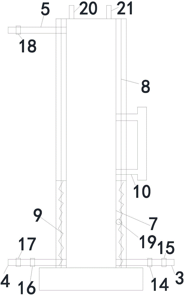
[0054] Such as image 3 As shown, the difference between this embodiment and Embodiment 1 is that the boiler in this embodiment includes a furnace cylinder, an insulation layer is arranged inside the furnace cylinder wall, and an electronic induction heating coil is arranged at the middle and lower part of the furnace cylinder wall, and the heating coil is connected with the furnace cylinder wall. The power supply is connected, the lower side of the furnace drum is provided with a water inlet pipe and the sewage pipe, the upper side of the furnace drum is provided with an outlet pipe, and the top of the furnace drum is provided with an electrode rod liquid level gauge.

Embodiment 3

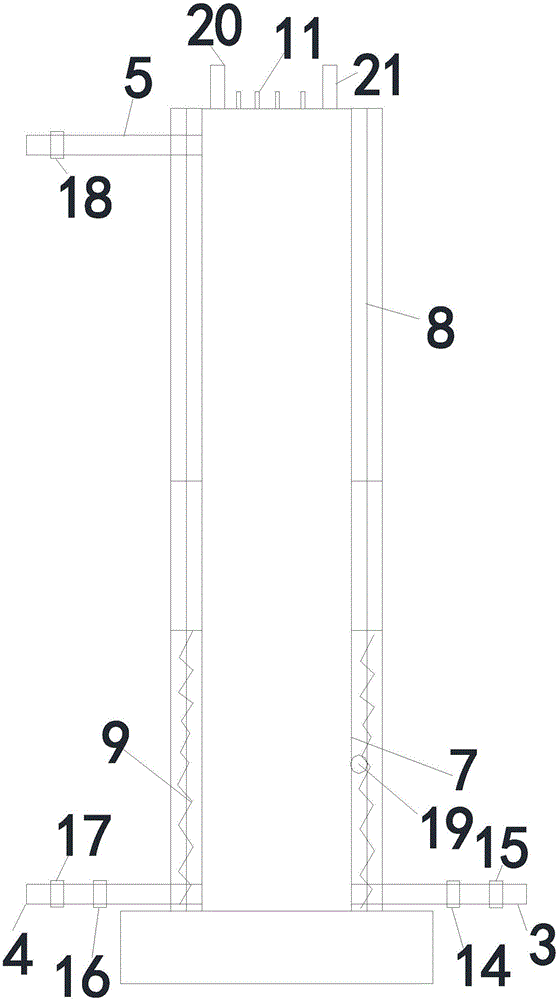
[0056] Such as Figure 4 As shown, the difference between this embodiment and Embodiment 1 is that the boiler in this embodiment includes a U-shaped furnace tube, an insulation layer is provided outside the furnace tube wall, and an electronic induction type is provided at the middle and lower part of the vertical part of the furnace tube wall. The heating coil, the water inlet pipe and the sewage pipe are arranged at the lateral part of the furnace wall, the gas outlet pipe is arranged on the upper side of the furnace cylinder, and the electrode rod liquid level gauge is arranged on the top of the furnace cylinder.

[0057] The electronic induction heating coil in this embodiment is arranged between the inner insulation layer and the outer insulation layer; the inner insulation layer includes two layers of heat insulation layers, and the outer insulation layer includes three layers of heat insulation layers. Gel insulation.

[0058] In this embodiment, a temperature sensor i...


PUM


Abstract

The invention discloses a boiler system adopting an electromagnetic induction type heating mode. The boiler system comprises a control room, wherein a controller is arranged in the control room; a plurality of boilers adopting the electromagnetic induction type heating mode are arranged in a heating room; each boiler is provided with a water inlet tube, a blow-off tube and a gas outlet branch tube; and the gas outlet branch tubes are gathered to a gas outlet header tube. The invention further discloses an implementation method for the boiler system adopting the electromagnetic induction type heating mode. The boiler system has characteristics of being simple in structure, low in manufacturing cost, convenient to manufacture, convenient to maintain, energy-saving and environmentally-friendly, high in heating speed, high in safety, convenient to popularize and the like.

Description

technical field [0001] The invention relates to high-pressure boiler technology, in particular to an electromagnetic induction heating boiler system and its realization method. Background technique [0002] Boiler is a kind of energy conversion equipment. The energy input to the boiler is in the form of chemical energy in fuel, electric energy, heat energy of high-temperature flue gas, etc. After conversion by the boiler, it outputs steam, high-temperature water or organic heat carrier with certain heat energy. . [0003] Existing boilers include an outer shell and an inner tank located inside the outer shell, and an insulating layer is filled between the outer shell and the inner tank, and are heated by organic fuel or electric heating tubes, but the structure in the prior art has the following technical problems: [0004] (1) Larger environmental pollution; [0005] (2), the energy conversion rate is low; [0006] (3), the heating rate is slow; [0007] (4), relatively...

Claims


Application Information

Patent Timeline
Patent Type & Authority Applications(China)
IPC IPC(8): F22B1/28F22B35/00F22B37/22F22B37/78F22B37/44F22B37/54
CPCF22B1/281F22B35/00F22B37/22F22B37/44F22B37/54F22B37/78
Inventor 陈才德
Owner 东阳市东德环保设备有限公司
Why Eureka
Try Eureka