
Heat simulation method for differential temperature rolling
A thermal simulation and differential temperature technology, applied in the field of metal material technology research, can solve the problems of decreased strain and temperature uniformity, decreased research accuracy, and different process conditions, and achieves low experimental cost, short experimental period, and sample size. small effect
- Summary
- Abstract
- Description
- Claims
- Application Information
AI Technical Summary
Problems solved by technology
Method used
Image

Examples
Embodiment Construction
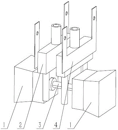
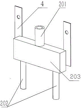
[0031] The method is based on a Gleeble thermal simulation testing machine, and an air jet cooling device 2 is added in the working cavity of the thermal simulation testing machine. see figure 1 , the jet cooling device 2 is two groups, which are symmetrically arranged between the two indenters 1 and the two ends of the sample 3 by means of the mounting frame 4, including the spray chamber 203 and the air inlet pipe 201 and the air outlet pipe 202 connected to the spray chamber 203, and the air inlet pipe 201 is connected to the cooling air source, and the air outlet of the air outlet pipe 202 faces the end of the sample 3 . In order to make the cooling uniform and enhance the cooling effect, two air outlet pipes 202 are installed symmetrically on both sides of the sample 3 . The gas jets of the gas outlet pipe 202 are 3 to 5 gas jet holes facing the sample, and the diameter of the gas jet holes is 0.5-1.5 mm, generally 1 mm.
[0032] The method is specifically carried out a...
PUM
 Abstract
Description
Claims
Application Information