Cryogenic liquid automatic filling system and method

A cryogenic liquid and automatic technology, which is applied in the field of air separation, can solve the problems of energy loss, large safety hazards, and the inability to realize automatic pump stop operation, etc., to achieve the effect of reducing product loss and cooling loss, and reducing product loss

Active Publication Date: 2016-10-19
上海宝闵工业气体有限公司
View PDF7 Cites 3 Cited by
  • Summary
  • Abstract
  • Description
  • Claims
  • Application Information

AI Technical Summary

Problems solved by technology

The opening and closing of liquid pumps and valves requires human intervention. This control method is more dependent on people, and the pressure is controlled based on experience. The operation process is more complicated. If the time is too long, it will cause energy loss; if the time is too short, the filling efficiency will be reduced
The time control of the cold pump is arbitrary. In the event of an emergency in the liquid filling process, there is no mandatory cut-off measure. Especially when filling gases with a high risk factor such as liquid oxygen and liquid hydrogen, m

Method used


Image

  • Cryogenic liquid automatic filling system and method

Examples


Example Embodiment

[0032] Embodiment one (order is 20 tons of liquid oxygen, liquid oxygen tank car filling)

[0033] 1) Set the filling target weight value of the weighing instrument at the filling position to 20,000kg, set the liquid level of the storage tank to be lower than 5% to stop filling, and the preset value of the outlet temperature of the filling pump to be -60°C. The pressure setting of the filling pipeline is 100KPa, and the preset cooling time of the filling pump is 1800 seconds;

[0034] 2) When the liquid oxygen tanker is driving on the weighing instrument (weighing floor scale) at the filling position, the controller judges that the filling condition is met, that is, the weighing instrument at the filling position displays a weight of 6380kg, which is greater than 5000kg (indicating that the filling container has been filled). in place); the filling pipeline pressure display is 230KPa, which is 100KPa higher than the set value (indicating that the filling hose is well connected...

Example Embodiment

[0039] Embodiment two (order is liquid nitrogen 15 tons, liquid nitrogen tank car filling)

[0040] 1) Set the filling target weight value of the weighing instrument at the filling position to 15,000kg, set the liquid level of the storage tank to be lower than 5% to stop filling, and the preset value of the outlet temperature of the filling pump to be -55°C. The set value of the filling pipeline pressure is 80KPa, and the preset cooling time of the filling pump is 1800 seconds;

[0041] 2) When the liquid nitrogen tanker is driving on the weighing instrument (weighing floor scale) at the filling position, the controller judges that the filling condition is met, that is, the weighing instrument at the filling position shows a weight of 58,000kg, which is greater than 5,000kg (indicating that the tanker already in place); the filling pipeline pressure display is 160KPa, which is 100KPa higher than the set value (indicating that the filling hose is well connected); the liquid level...


PUM


Abstract

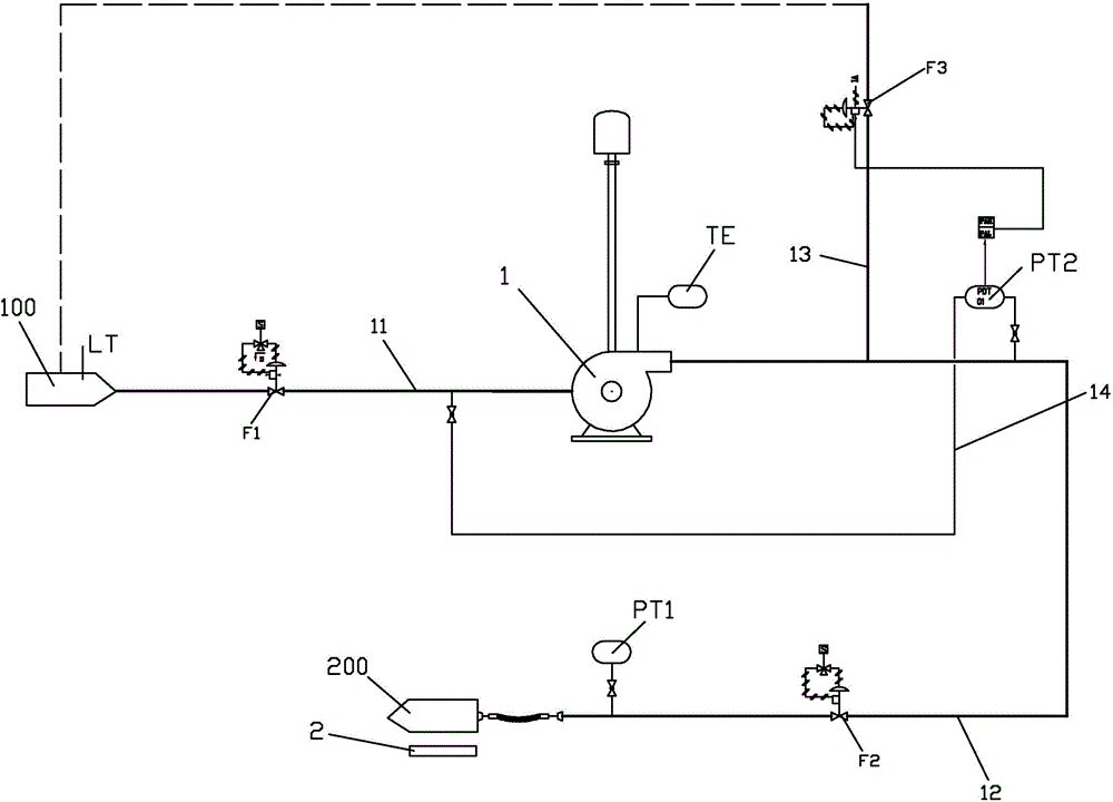
The invention provides a cryogenic liquid automatic filling system and method. The filling system includes a filling pump; an inlet pipe is connected with a storage tank, and provided with an inlet control valve; two paths of the outlet pipes of the filling pump are provided, wherein one filling pipe is connected to a filling position, and a reflux pipe is connected to the filling pipe and returns back to the storage tank; the filling pipe is provided with an outlet control valve, and a pressure difference transmitter is arranged on the filling pipeline near the filling position; the reflux pipe is provided with a reflux valve; a weighing device is arranged in the filling position; a liquid level gauge is arranged in the storage tank; a thermometer is arranged on the filling pump; and a controller is respectively electrically connected with the inlet control valve, the outlet control valve, the pressure difference transmitter, the reflux valve, the weighing device, the liquid level meter and the thermometer. The cryogenic liquid automatic filling system and method automatically realize precooling and filling; and the filling process is stable, safe and efficient, and greatly reduces labor costs.

Description

technical field [0001] The invention relates to air separation technology, in particular to a cryogenic liquid automatic filling system and method. Background technique [0002] With the continuous development of the national economy and the continuous improvement of the industrialization process, the gas industry has developed rapidly, and the market demand for cryogenic liquids has continued to rise. The current means of transportation for cryogenic liquids is mainly high-vacuum cryogenic tankers. Due to the high production cost of cryogenic liquids, during the transportation of liquids, the loss of cryogenic liquids should be strictly controlled to ensure the accuracy of filling volume and improve the safety operation awareness and operation skills of filling personnel. [0003] There are two main filling methods for cryogenic liquid tankers: pressure transmission (self-pressurized transmission) and filling pump filling. Pressure filling is to use the evaporator to vapo...

Claims


Application Information

Patent Timeline
IPC IPC(8): F17C5/02F17C13/02F17D1/02F17D3/01
Inventor 邢世钦李祖兵唐文彬徐锋
Owner 上海宝闵工业气体有限公司
Why Eureka
Try Eureka