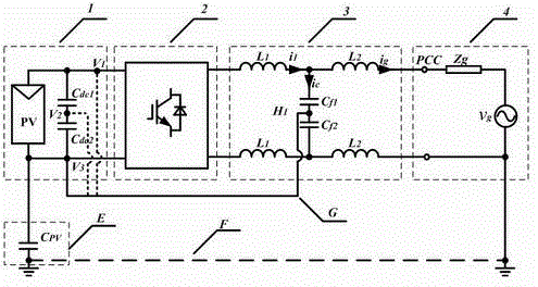
LCL non-isolation type grid-connected inverter system
An inverter, non-isolated technology, applied in the field of LCL non-isolated grid-connected inverter system, to achieve the effects of easy implementation, improved grid current quality, and reduced voltage stress
- Summary
- Abstract
- Description
- Claims
- Application Information
AI Technical Summary
Problems solved by technology
Method used
Image
Examples
Embodiment 1
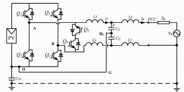
[0025] The following is a detailed description of the LCL non-isolated grid-connected inverter system of the HERIC circuit combined with the inverter, such as figure 2 The shown HERIC circuit includes a first bridge arm, a second bridge arm and a switch unit; the switch unit includes a switch tube Q 5 and Q 6 ; The above switch tube Q 5 The emitter is connected to the midpoint A of the first bridge arm, and the above-mentioned switching tube Q 6 The emitter of the second bridge arm is connected to point B, the switch tube Q 5 The collector and switch tube Q 6 connected to the collector; the inverter is connected to the filter, specifically, the inverter side inductance is divided into two identical inductances connected in parallel; the upper inverter side inductance is connected to the switching tube Q 5 The emitter, the lower inverter side inductor is connected to the switching tube Q 6 the emitter.
[0026] In this embodiment, the LCL filter capacitor C f1 with C f...
Embodiment 2
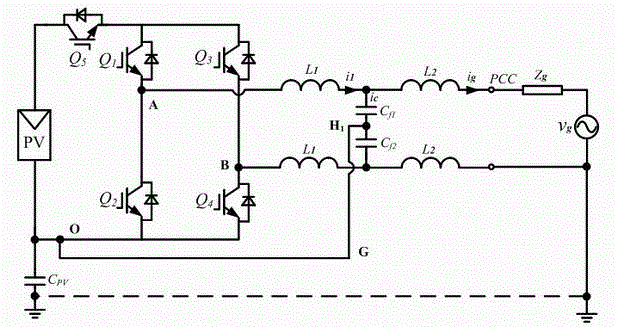
[0038] Such as image 3 Shown is the structure diagram of the LCL non-isolated grid-connected inverter system combined with the H5 topology, including the first bridge arm, the second bridge arm and the switching unit; the switching unit includes the switching tube Q 5 ; The switching tube Q 5 The emitter of the inverter is connected to the upper ends of the two bridge arms, and the collector is connected to the positive end of the photovoltaic panel; the inverter topology is connected to the filter, specifically, the inverter side inductance is divided into two identical inductances connected in parallel, The upper inverter side inductance is connected to point A of the first bridge arm, and the lower inverter side inductance is connected to point B of the second bridge arm; the filter capacitor C of the LCL type filter f1 with C f2 Node H 1 Connect with point O.
Embodiment 3
[0040] Such as Figure 4 Shown is the structure diagram of the LCL non-isolated grid-connected inverter system combined with the H6 topology, including the first bridge arm, the second bridge arm and the diode D 1 、D 2 ; The first bridge arm includes a switching tube Q 1 , Q 3 and Q 5 ; The second bridge arm includes a switching tube Q 2 , Q 4 and Q 6 ; The diode D 1 The anode and cathode of the switch are respectively connected to the switch Q 4 the emitter and Q 3 collector; the diode D 2 The anode and cathode of the switch are respectively connected to the switch Q 3 the emitter and Q 4 The collector of the inverter; the inverter topology is connected to the filter, specifically, the inverter side inductance is divided into two identical inductances connected in parallel, the upper inverter side inductance is connected to point A of the first bridge arm, and the lower inverter side is connected to point A of the first bridge arm. The inductance on the transforme...
PUM
 Abstract
Description
Claims
Application Information
 - R&D
- Intellectual Property
- Life Sciences
- Materials
- Tech Scout
- Unparalleled Data Quality
- Higher Quality Content
- 60% Fewer Hallucinations
Browse by: Latest US Patents, China's latest patents, Technical Efficacy Thesaurus, Application Domain, Technology Topic, Popular Technical Reports.
© 2025 PatSnap. All rights reserved.Legal|Privacy policy|Modern Slavery Act Transparency Statement|Sitemap|About US| Contact US: help@patsnap.com


