
Spine vertebral plate bridging system

A lamina bridge and spine technology, applied in the field of spine lamina bridge system, can solve the problems of stress shielding, unfavorable lamina molding growth, artifacts affecting clinical observation, etc., to reduce side effects, excellent biocompatibility, good long-term effect

Inactive Publication Date: 2016-10-26
广州聚生生物科技有限公司
View PDF12 Cites 3 Cited by
  • Summary
  • Abstract
  • Description
  • Claims
  • Application Information

AI Technical Summary

Problems solved by technology

[0003] At present, the existing spinal laminar bridging systems have different shapes, and the long-term effects in the later stage are also different. In terms of material selection, all of them are medical titanium alloys. After the metal laminar system is implanted into the human body, there are stress shielding, CT and Defects such as artifacts affecting clinical observation during MR examination
After the metal lamina bridging system is implanted, the rigidity and hardness of the metal system itself is used to actively apply a long-term support force or pulling force to the lamina side. This force makes the lamina passively shaped and fixed, and internal stress exists for a long time. , is not conducive to the formation and growth of the lamina itself

Method used


Image

  • Spine vertebral plate bridging system
  • Spine vertebral plate bridging system
  • Spine vertebral plate bridging system

Examples


Embodiment Construction

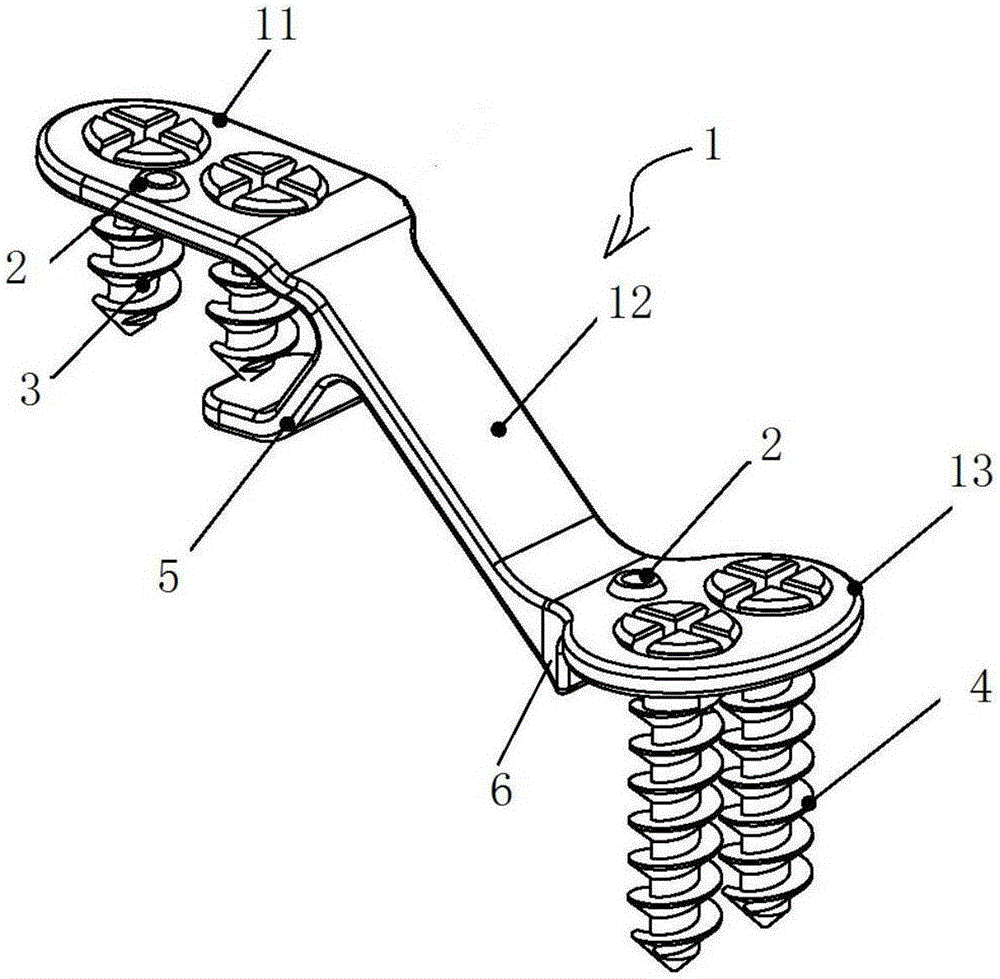
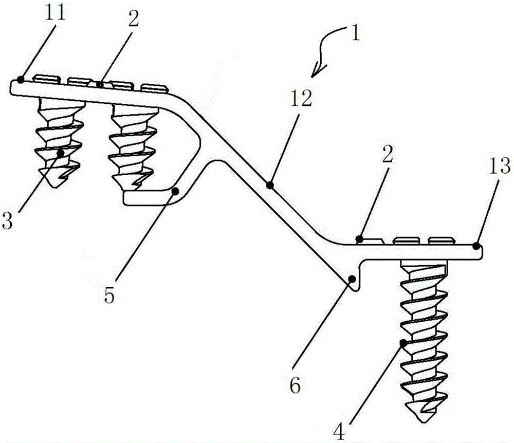
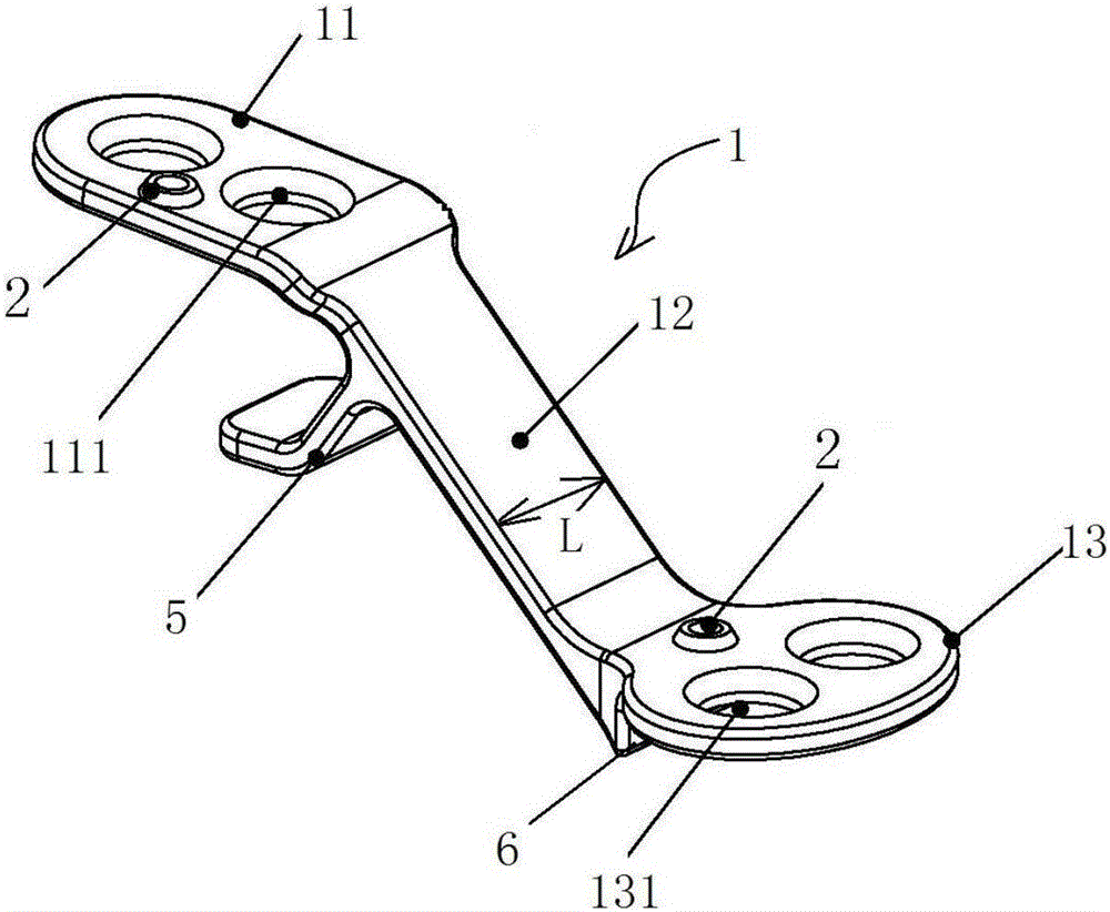
[0039] Such as Figure 1 to Figure 5 As shown, the spinal lamina bridging system includes a fixed plate main body 1, a developing marker 2, short bone screws 3 and long bone screws 4. The fixed plate main body 1 consists of a lamina fixed end 11, an inclined support rib 12 and a side mass fixed end 13. Connected, and the whole is a kind of "Z" shape, two straight through holes 111 are arranged on the fixed end 11 of the lamina, the short bone nails 3 are matched with the straight through holes 111, and the fixed end 13 of the side block is provided with Two horizontal through holes 131, the long bone nail 4 cooperates with the horizontal through holes 131. The short bone nail 3 is provided with an initial self-tapping cutting edge 31 . The long bone nail 4 is provided with an initial self-tapping cutting edge 41 .

[0040] In the present invention, the main body 1 of the fixed plate adopts an ultra-thin design, specifically: the fixed end 11 of the lamina, the inclined suppo...


PUM

PropertyMeasurementUnit
Thicknessaaaaaaaaaa
Maximum widthaaaaaaaaaa
Lengthaaaaaaaaaa

Abstract

The invention relates to a spinal lamina bridging system, comprising a main body of a fixing plate, a developing marker, short bone screws and long bone screws. One type of "Z" shape, two straight through holes are set on the fixed end of the lamina, the short bone nails are matched with the straight through holes, two horizontal through holes are set on the fixed end of the side block, and the long bone nails are matched with the horizontal through holes. Through-hole fit, the fixed end of the lamina, the inclined support rib and the fixed end of the side block have the same thickness, which is 0.8mm to 1.0mm; the width of the inclined support rib is smaller than the maximum width of the fixed end of the lamina and the maximum width of the fixed end of the side block; the inclined surface The width of the supporting rib is 4.5mm-5mm; the maximum width of the fixed end of the lamina is 6mm-10mm; the maximum width of the fixed end of the lateral mass is 6mm-10mm. The system of the present invention has good elasticity, and can better fit the bone surface under screw pressure.

Description

technical field [0001] The invention relates to the technical field of medical instruments, in particular to a spinal vertebra laminar bridging system. Background technique [0002] Due to various factors such as developmental spinal stenosis, cervical spondylosis, cervical intervertebral disc herniation, posterior longitudinal ligament osteoarthritis, and hypertrophy of the ligamentum flavum, etc., the human spinal canal often causes spinal canal stenosis, compresses the spinal cord and causes axial pain, pain and numbness of the limbs Symptoms such as muscle weakness and even paralysis seriously affect life. For the above-mentioned diseases, the use of laminoplasty is an effective method for expanding the spinal canal. Single-door laminoplasty is the most common laminoplasty at present. At present, the laminar bridging system has been widely used in the reconstruction of the lamina in open laminoplasty. It can expand the spinal canal, support and protect the rear structu...

Claims


Application Information

Patent Timeline
IPC IPC(8): A61B17/88A61B17/70
CPCA61B17/70
Inventor 程顺巧张培发余振
Owner 广州聚生生物科技有限公司
Learn More