
Linear tank-shaped needleless electrostatic spinning device and spinning method

An electrospinning, straight-line technology, applied in textiles and papermaking, filament/thread forming, fiber processing, etc., can solve the problem of the stability of nanofiber preparation that affects the concentration of spinning solution, the preparation of nanofibers is not smooth, and the design process is complicated and other problems, to achieve the effect of solving the complex structure design of the nozzle, realizing automatic and accurate supply, and simple structure design

Inactive Publication Date: 2016-10-26
DONGHUA UNIV +1
View PDF10 Cites 21 Cited by
  • Summary
  • Abstract
  • Description
  • Claims
  • Application Information

AI Technical Summary

Problems solved by technology

However, the porous spinneret has a three-layer structure, which has the problems of complex design process and high processing difficulty.
Patent CN 103088443 A discloses an umbrella-shaped electrospinning nozzle and an electrospinning method. This method can realize the batch preparation of nanofibers, but the biggest disadvantage is that the nozzle is in the electrospinning process, and the polymer spinning The silk liquid is in contact with the atmospheric environment in a large area, and the solvent is extremely volatile, which will seriously affect the concentration of the spinning liquid and the stability of nanofiber preparation; patent CN 101003916 A discloses a jet method for mass production of nanofibers. Electrospinning device, the device generates jets by injecting air at the bottom of the liquid tank to form bubbles on the free liquid surface of the polymer. This method can realize the large-scale production of nanofibers, but the jets formed by the bubbles are easy to produce in the spinning process. Unstable problems occur, and at the same time, the solvent of the exposed polymer spinning solution is extremely volatile, which leads to unsmooth preparation of nanofibers in the later stage

Method used


Image

  • Linear tank-shaped needleless electrostatic spinning device and spinning method
  • Linear tank-shaped needleless electrostatic spinning device and spinning method
  • Linear tank-shaped needleless electrostatic spinning device and spinning method

Examples


Embodiment 1

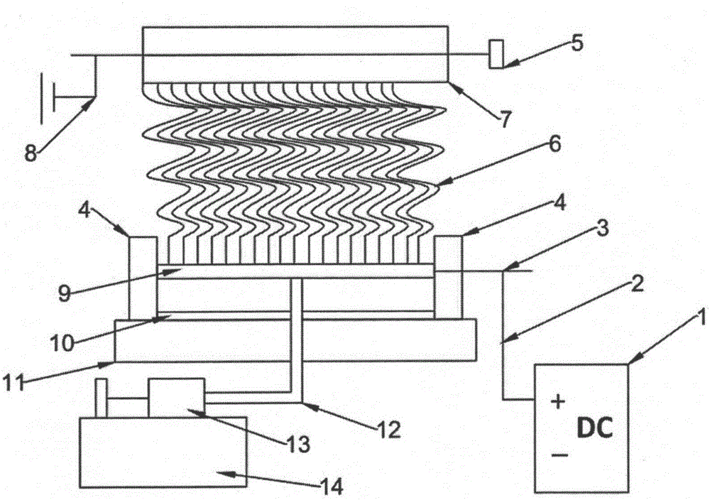
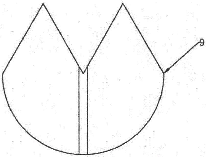
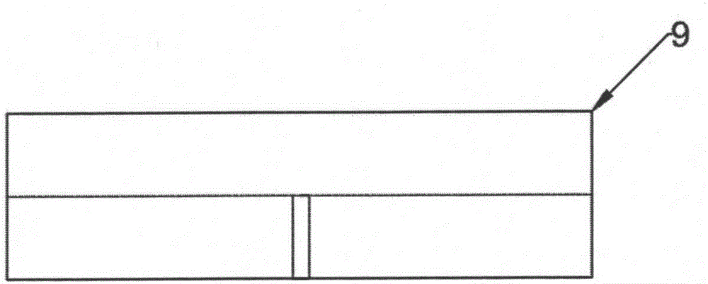
[0046] Next, nanofibers are prepared by using a polymer solution prepared from polyacrylonitrile (PAN) and N,N dimethylformamide (DMF). The mass fraction of the prepared PAN polymer solution is 12%. Fix the linear groove-shaped nozzle 9 horizontally on the brackets 4 at both ends, and fix the brackets 4 at both ends vertically on the polytetrafluoroethylene plate 11, place the solution recovery tank 10 directly below the linear groove-shaped nozzle 9, and metal screws 3 is connected to the linear groove-shaped nozzle 9, the metal screw 3 is connected to the positive electrode of the high-voltage electrostatic generator 1 through the metal wire 2, one end of the infusion tube 12 is connected to the micropore at the bottom center of the linear groove-shaped nozzle 9, and the other end is connected to the medical syringe 13 is connected, and the solution flow rate of the medical syringe 13 is controlled by the micro-injection pump 14. The cylindrical metal roller 7 for collectin...

Embodiment 2

[0048] Fix the linear groove-shaped nozzle 9 horizontally on the brackets 4 at both ends, and fix the brackets 4 at both ends vertically on the polytetrafluoroethylene plate 11, place the solution recovery tank 10 directly below the linear groove-shaped nozzle 9, and metal screws 3 is connected to the linear groove-shaped nozzle 9, the metal screw 3 is connected to the positive electrode of the high-voltage electrostatic generator 1 through the metal wire 2, one end of the infusion tube 12 is connected to the micropore at the bottom center of the linear groove-shaped nozzle 9, and the other end is connected to the medical syringe 13 is connected, and the solution flow rate of the medical syringe 13 is controlled by the micro-injection pump 14. The cylindrical metal roller 7 for collecting nanofibers is connected to the speed regulating motor 5 , and the cylindrical metal roller 7 is connected to the ground wire 8 . Set the vertical distance from the linear trough nozzle to the...

Embodiment 3

[0050] Fix the linear groove-shaped nozzle 9 horizontally on the brackets 4 at both ends, and fix the brackets 4 at both ends vertically on the polytetrafluoroethylene plate 11, place the solution recovery tank 10 directly below the linear groove-shaped nozzle 9, and metal screws 3 is connected to the linear groove-shaped nozzle 9, the metal screw 3 is connected to the positive electrode of the high-voltage electrostatic generator 1 through the metal wire 2, one end of the infusion tube 12 is connected to the micropore at the bottom center of the linear groove-shaped nozzle 9, and the other end is connected to the medical syringe 13 is connected, and the solution flow rate of the medical syringe 13 is controlled by the micro-injection pump 14. The cylindrical metal roller 7 for collecting nanofibers is connected to the speed regulating motor 5 , and the cylindrical metal roller 7 is connected to the ground wire 8 . Set the vertical distance from the linear trough nozzle to the...


PUM

PropertyMeasurementUnit
Lengthaaaaaaaaaa
Diameteraaaaaaaaaa
Diameteraaaaaaaaaa

Abstract

The invention relates to a linear tank-shaped needleless electrostatic spinning device and a spinning method. The device comprises a solution supply system, a spray head system, a solution recycling device and a nanofiber collection system. The solution supply system supplies a solution by controlling an injector through a micro-injection pump; spray heads are linear tank-shaped copper bars; the solution recycling device is a solution tank with the equal length as the copper bar spray heads; the nanofiber collection system is a grounded cylindrical metal roller driven by an adjustable-speed motor. According to the device, the high polymer solution can be automatically and precisely supplied by adopting the micro-injection pump solution supply system; through the linear tank-shaped spray head structure, the problems that when a traditional single needle is adopted, the solution is prone to block, and the nanofiber yield is low are avoided, the purpose of simultaneously forming multiple pieces of jet flow can be achieved, the nanofiber yield in unit time is greatly increased, continuous nanofiber preparation is achieved, and an industrial nanofiber production prospect is achieved.

Description

technical field [0001] The invention belongs to the technical field of nano electrospinning and textile machinery, and in particular relates to a linear groove-shaped needle-free electrospinning device and a spinning method using the device. Background technique [0002] Since Formalas invented the electrospinning experimental device in 1934 and applied for a number of patents, the electrospinning technology has aroused the interest of many scientific researchers. The reason is that this technology can not only prepare submicron or even nanoscale materials, but also The structure, performance and morphology of the desired functional material can be regulated conveniently by controlling the process parameters. The successful preparation of nanofibers is the best example. In recent years, with the rapid development of nanotechnology and functional materials, the design of electrospinning devices and the study of process parameters have become a research hotspot in the field o...

Claims


Application Information

Patent Timeline
IPC IPC(8): D01D5/00
CPCD01D5/0061D01D5/0069D01D5/0076D01D5/0092
Inventor 覃小红魏亮王荣武
Owner DONGHUA UNIV
Learn More