Cavity-backed ultra-wideband antenna device

An ultra-broadband antenna and cavity-backed technology, which is applied in antennas, electrical long antennas, non-resonant long antennas, etc., can solve problems such as welding difficulties and high feeding accuracy requirements

Inactive Publication Date: 2016-10-26
HARBIN INST OF TECH AT WEIHAI
View PDF8 Cites 4 Cited by
  • Summary
  • Abstract
  • Description
  • Claims
  • Application Information

AI Technical Summary

Problems solved by technology

[0004] Aiming at the shortcomings and deficiencies in the prior art, the present invention proposes a structure that is reasonable, avoids the traditional logarithmic periodic antenna’s problems of high feeding accuracy and welding difficulties at the high-frequency vibrator end, and also controls the cost. Cavity-backed ultra-wideband antenna device

Method used


Image

  • Cavity-backed ultra-wideband antenna device
  • Cavity-backed ultra-wideband antenna device
  • Cavity-backed ultra-wideband antenna device

Examples


Embodiment Construction

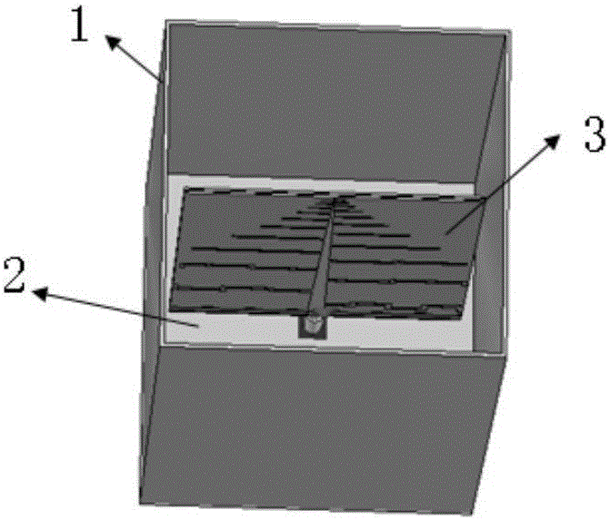
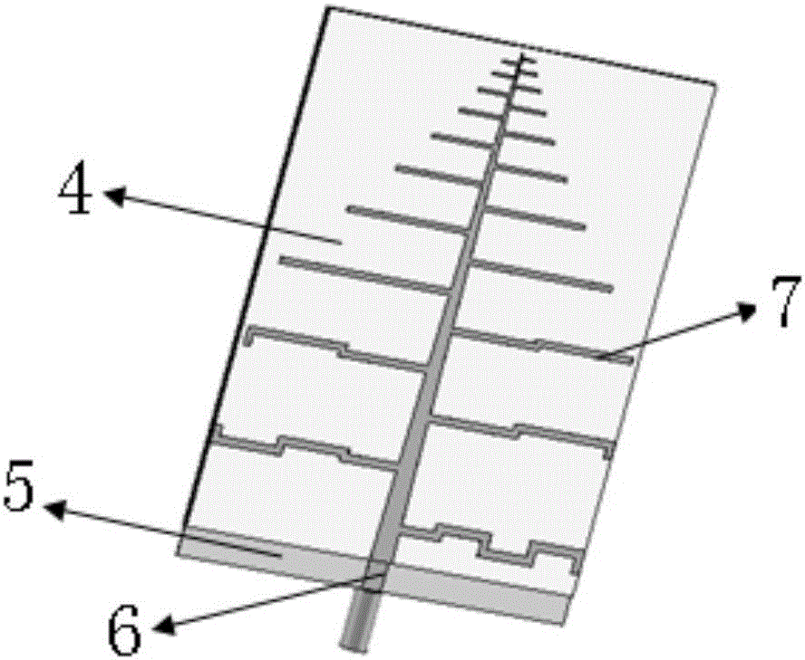
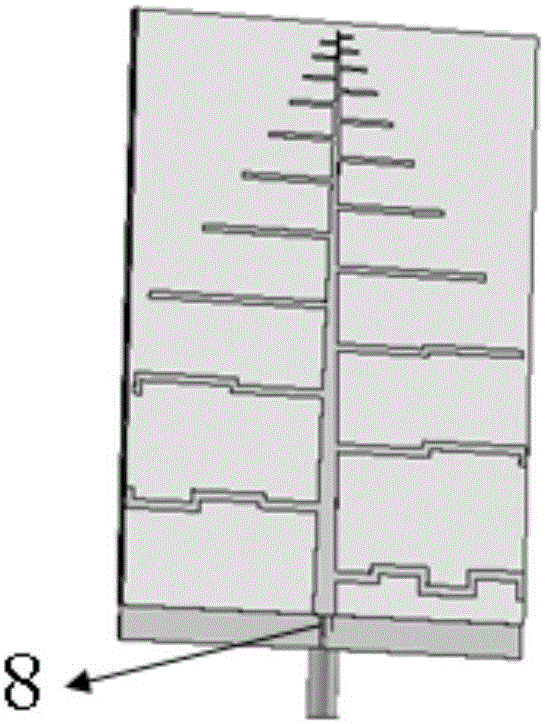
[0034] The invention designs a specific ultra-broadband cavity-backed antenna device, and uses full-wave electromagnetic simulation software to simulate the performance of the antenna. The vibrator length of the designed logarithmic periodic antenna is about 71.5 mm, and the low-frequency vibrator is treated with meandering lines to achieve miniaturization. The return loss characteristics of log-periodic antenna ports are as follows: Figure 7As shown in the figure, it can be seen that the average return loss of the antenna is small in the frequency range of 2GHz to 6GHz, which meets the VWR requirements of the ultra-wideband antenna, and has good VSWR performance near the frequency of 1GHz.

[0035] In order to characterize the radiation characteristics of the antenna, two main planes are selected here, one is the xoy plane and the other is the yoz plane, and the simulation results of the radiation gain pattern and the axial ratio pattern in the two main planes are given resp...


PUM


Abstract

The invention relates to the technical field of microwaves and antennas, and particularly discloses a cavity-backed ultra-wideband antenna device used in radio systems such as radar and communication. The cavity-backed ultra-wideband antenna device is characterized by being provided with a small log-periodic antenna, a metal cavity and a wideband microwave wave-absorbing material layer, wherein the small log-periodic antenna is arranged in the metal cavity; the wideband microwave wave-absorbing material layer is arranged at the bottom of the inner side of the metal cavity; and the small log-periodic antenna is of a micro-strip printed circuit structure. Compared with the prior art, the cavity-backed ultra-wideband antenna device has the obvious advantages of small size, low cost and the like.

Description

Technical field: [0001] The invention relates to the technical field of microwaves and antennas, in particular to a cavity-backed ultra-wideband antenna device used in radio systems such as radar and communication. Background technique: [0002] Common types of ultra-wide antennas include planar equiangular helix, planar Archimedes helix, tapered slot antenna, log-periodic, sinusoidal antenna, ultra-wideband monopole antenna, and ultra-wideband slot antenna. The planar equiangular helical antenna is a frequency-independent antenna, which was first proposed by Rumsey and Dyson et al. Now it is widely used in broadband passive direction finding systems. The planar Archimedes spiral antenna was proposed in the 1950s. The Archimedes spiral antenna has the characteristics of wide frequency band, circularly polarized radiation, pattern shape and input impedance change with frequency, large half-power lobe width, and small aperture surface. It can be installed flush and belongs to...

Claims


Application Information

Patent Timeline
Patent Type & Authority Applications(China)
IPC IPC(8): H01Q1/36H01Q1/38H01Q11/10
CPCH01Q1/38H01Q1/36H01Q11/105
Inventor 宋立众薛敬宏谢春华
Owner HARBIN INST OF TECH AT WEIHAI
Why Eureka
Try Eureka