
Electrolytic capacitor-free photovoltaic inverter capable of suppressing leakage current and control method for photovoltaic inverter

A photovoltaic inverter, electrolytic capacitor technology, applied in photovoltaic power generation, conversion of AC power input to DC power output, electrical components, etc. large problems, to achieve the effect of reducing leakage current, long service life, and reducing inductance value

Inactive Publication Date: 2016-10-26
YANSHAN UNIV
View PDF4 Cites 12 Cited by
  • Summary
  • Abstract
  • Description
  • Claims
  • Application Information

AI Technical Summary

Problems solved by technology

[0005] The disadvantage of the single-phase current-source inverter is that the DC current fluctuates greatly, and its fluctuation frequency is twice the frequency of the grid, which directly leads to a higher third harmonic in the grid-connected current, which seriously affects the current quality of the grid. The DC current is as smooth as possible, and a DC inductance with a large inductance is often connected in series on the DC side, resulting in an increase in system volume, increase in cost, and decrease in efficiency.

Method used


Image

  • Electrolytic capacitor-free photovoltaic inverter capable of suppressing leakage current and control method for photovoltaic inverter
  • Electrolytic capacitor-free photovoltaic inverter capable of suppressing leakage current and control method for photovoltaic inverter
  • Electrolytic capacitor-free photovoltaic inverter capable of suppressing leakage current and control method for photovoltaic inverter

Examples


Embodiment Construction

[0033] The specific implementation manners of the present invention will be described in further detail below in conjunction with the accompanying drawings.

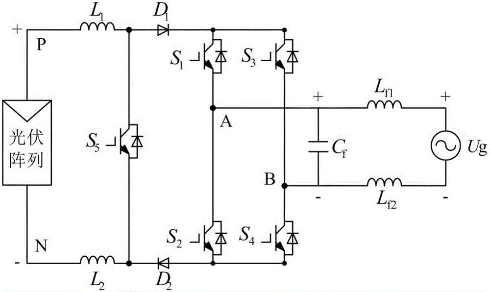
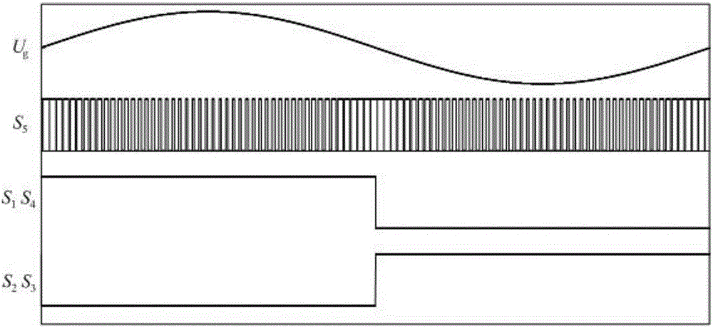
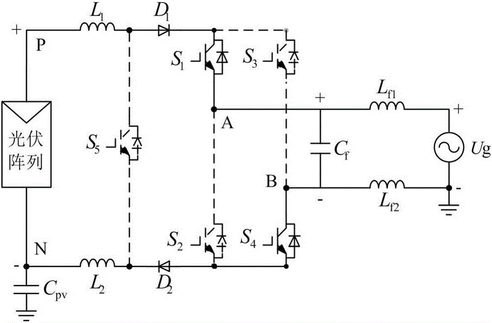
[0034] figure 1 Shown is a topological structure of a non-electrolytic capacitor photovoltaic inverter capable of suppressing leakage current of the present invention, which mainly consists of a photovoltaic cell array module, five power switch tubes, two power diodes, and two identical DC energy storage inductors , two identical filter inductors and a filter capacitor; the first DC energy storage inductor L 1 One end is connected to the "+" end of the photovoltaic cell array module, and the other end is respectively connected to the fifth power switch tube S 5 anode of the first power diode D 1 The anode connection of the second DC energy storage inductor L 2 One end of it is connected to the "-" end of the photovoltaic cell array module, and the other end is respectively connected to the fifth power switch tube S 5...


PUM


Abstract

The invention discloses an electrolytic capacitor-free photovoltaic inverter capable of suppressing a leakage current and a control method for the photovoltaic inverter. The photovoltaic inverter consists of a photovoltaic cell array module, five power switch transistors, two power diodes, two same direct-current energy storage inductors, two same filter inductors and one filter capacitor. According to the photovoltaic inverter and the control method, the inverter topology is free of an electrolytic capacitor, so that the service life is relatively long and the grid connection of a single-stage inverter can be realized; in the five power switch transistors, the four power switch transistors are in a power frequency mode, the one power switch transistor is in a high frequency mode, and only one power switch transistor is in the high frequency mode at any moment, so that the loss of the power switch transistor is greatly reduced and the system efficiency is relatively high; the grid-connected inverter adopts an area equivalence principle-based PWM modulation policy, so that on the premise of ensuring the quality of a grid-connected current, the values of the direct-current energy storage inductors are effectively reduced and the system volume and cost are reduced; and the topology and the control method therefor can ensure a constant common-mode voltage so as to effectively reduce the leakage current.

Description

technical field [0001] The invention belongs to the field of photovoltaic grid-connected power generation, and in particular relates to a non-electrolytic capacitor photovoltaic inverter capable of suppressing leakage current and a control method thereof. Background technique [0002] Photovoltaic grid-connected power generation is mostly realized by low-frequency transformer isolation. Isolated grid-connected can realize electrical isolation between the grid and photovoltaic cells to ensure personal safety. At the same time, it can provide voltage matching, suppress the DC component of grid-connected current, and eliminate leakage current simply and effectively. However, the low-frequency transformer increases the volume, weight and cost of the system, and reduces the conversion efficiency. Therefore, the non-isolated grid-connected power generation method without transformers has quickly attracted the attention of researchers from various countries and the attention of the...

Claims


Application Information

Patent Timeline
IPC IPC(8): H02M7/537
CPCH02J3/383H02M7/537Y02E10/56
Inventor 王立乔张晓飞董子亮
Owner YANSHAN UNIV
Learn More