
Surface treatment method of sic substrate, method of manufacturing sic substrate and semiconductor

一种表面处理、基板的技术,应用在半导体/固态器件制造、半导体器件、处理后等方向,能够解决SiC基板研磨损伤等问题

Active Publication Date: 2019-10-08
TOYOTA TSUSHO
View PDF7 Cites 0 Cited by
  • Summary
  • Abstract
  • Description
  • Claims
  • Application Information

AI Technical Summary

Problems solved by technology

However, due to mechanical polishing, polishing damage occurs on the surface of the SiC substrate

Method used


Image

  • Surface treatment method of sic substrate, method of manufacturing sic substrate and semiconductor
  • Surface treatment method of sic substrate, method of manufacturing sic substrate and semiconductor
  • Surface treatment method of sic substrate, method of manufacturing sic substrate and semiconductor

Examples


Embodiment Construction

[0048] Hereinafter, embodiments of the present invention will be described with reference to the drawings.

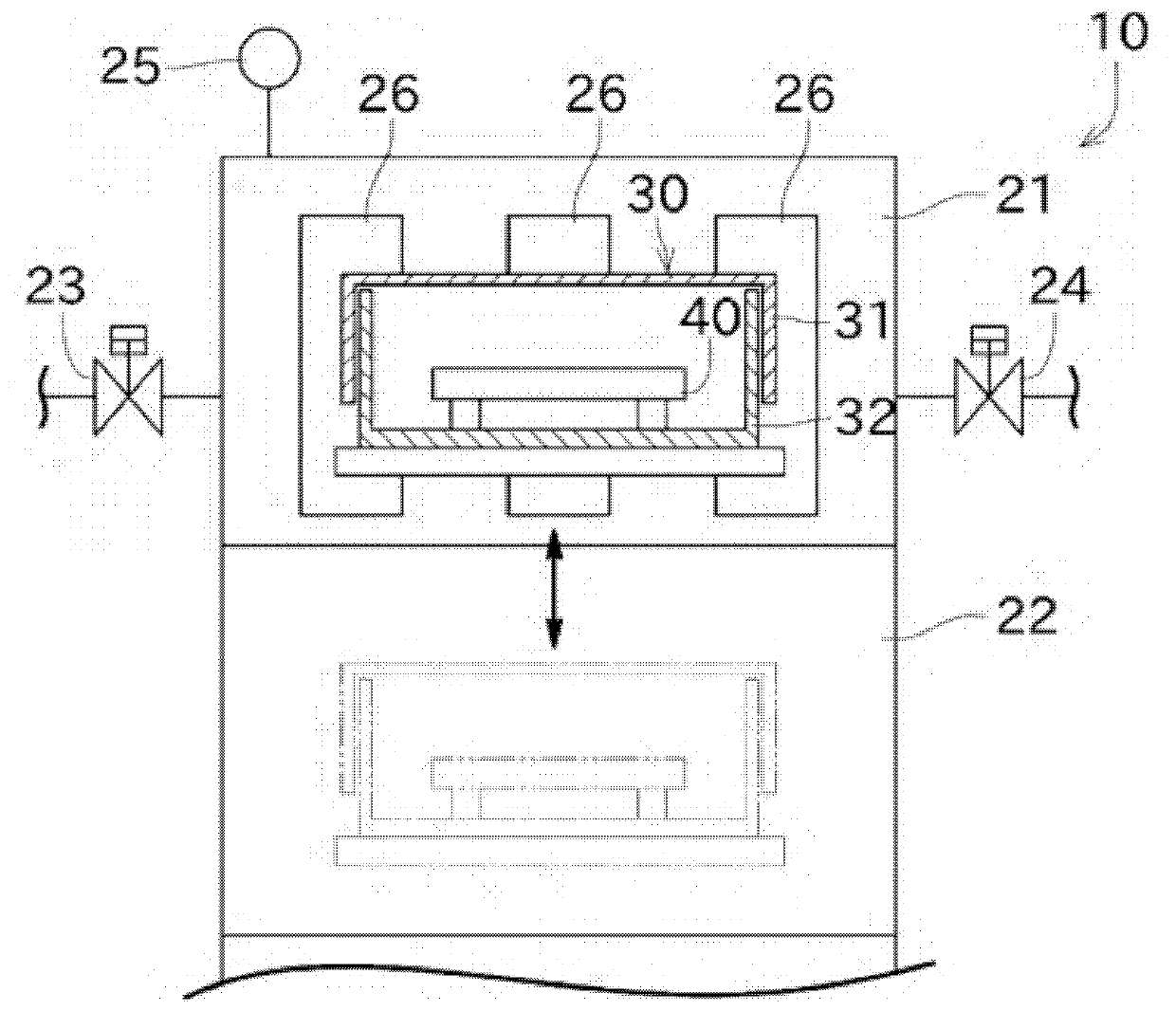
[0049] First, refer to figure 1 The high-temperature vacuum furnace 10 used for the heat treatment of this embodiment will be described. figure 1 It is a figure explaining the outline|summary of the high temperature vacuum furnace used for the surface treatment method of this invention.

[0050] Such as figure 1 As shown, the high-temperature vacuum furnace 10 has a main heating chamber 21 and a preliminary heating chamber 22 . The main heating chamber 21 can heat a SiC substrate having at least a surface made of single crystal SiC to a temperature of 1000° C. or higher and 2300° C. or lower. The preliminary heating chamber 22 is a space for performing preliminary heating before the main heating chamber 21 heats the SiC substrate.

[0051] The main heating chamber 21 is connected to a vacuum forming valve 23 , an inert gas injection valve 24 and a vacuum gauge 25 . ...


PUM

PropertyMeasurementUnit
roughnessaaaaaaaaaa
roughnessaaaaaaaaaa
roughnessaaaaaaaaaa

Abstract

When etching the SiC substrate ( 40 ) by heating the machined SiC substrate ( 40 ) in a SiC atmosphere, the etching rate is controlled by adjusting the pressure of the inert gas around the SiC substrate ( 40 ). Thereby, when latent flaws and the like exist on the SiC substrate (40), the latent flaws and the like can be removed. Therefore, even if epitaxial growth, heat treatment, etc. are performed, the surface of the SiC substrate (40) will not be rough, so a high-quality SiC substrate can be manufactured.

Description

technical field [0001] The invention mainly relates to a surface treatment method for removing latent damage of a SiC substrate. Background technique [0002] SiC is attracting attention as a new semiconductor material because it is superior in heat resistance, mechanical strength, etc. compared with Si and the like. [0003] Patent Document 1 discloses a surface treatment method for planarizing the surface of the SiC substrate. In this surface treatment method, a SiC substrate is accommodated in a storage container, and the storage container is heated while the inside of the storage container is brought under Si vapor pressure. Thereby, the SiC substrate inside the storage container is etched, and a molecularly flat SiC substrate can be obtained. [0004] Here, the SiC substrate is obtained by cutting out at a predetermined angle from an ingot made of single crystal SiC. Since the surface roughness is large in the cut out state, it is necessary to perform mechanical poli...

Claims


Application Information

Patent Timeline
Patent Type & Authority Patents(China)
IPC IPC(8): H01L21/302C30B29/36C30B33/08H01L21/205H01L21/265
CPCC30B29/36C30B33/08H01L21/302C30B25/20H01L21/02378H01L21/02433H01L21/02529H01L21/02661H01L21/3065H01L21/02019H01L21/3247H01L29/1608H01L21/265C30B25/10C30B25/186H01L21/0475
Inventor 鸟见聪矢吹纪人野上晓
Owner TOYOTA TSUSHO
Learn More