Power amplifier control circuit

A power amplifier and control circuit technology, applied in the microwave field, can solve problems such as improving the amplifier, informing the user of the alarm signal, and the circuit does not have a program control function, so as to improve stability and reliability, improve intelligence and automation, and improve self-protection effect of ability

Active Publication Date: 2016-11-02
CHINA ELECTRONIS TECH INSTR CO LTD
View PDF6 Cites 6 Cited by
  • Summary
  • Abstract
  • Description
  • Claims
  • Application Information

AI Technical Summary

Problems solved by technology

The advantage of this circuit is that it is simple in principle and easy to implement, but its single function can only meet the basic requirements of power amplifiers in simple environments. For relatively complex application environments such as radar, communication, electronic countermeasures, navigation and aerospace, this circuit The function of the function can no longer meet its usage requirements
[0005] The existing power amplifier control circuit has a simple principle and a single function, and its disadvantages mainly include the following points:
[0006] 1. The circuit does not have an internal amplitude stabilization function, so the flatness of the output power of the amplifier cannot be improved through the circuit. The flatness of the output power of the entire amplifier depends entirely on the performance of the power amplifier chip. Therefore, for environments with high requirements for flatness of output power , the circuit no longer applies
[0007] 2. The circuit does not have a program control function and only supports manual adjustment of the amplifier, which not only increases the cost of use, but also cannot meet the increasingly high requirements for equipment automation
[0008] 3. The circuit does not have an abnormal state monitoring function. Once the power amplifier fails, it cannot notify the user through an alarm signal, let alone perform automatic processing, and it is difficult to guarantee the stability and reliability of the system operation.

Method used


Image

  • Power amplifier control circuit
  • Power amplifier control circuit
  • Power amplifier control circuit

Examples


Embodiment Construction

[0028] The following will clearly and completely describe the technical solutions in the embodiments of the present invention with reference to the accompanying drawings in the embodiments of the present invention. Obviously, the described embodiments are only some, not all, embodiments of the present invention. Based on the embodiments of the present invention, all other embodiments obtained by persons of ordinary skill in the art without making creative efforts belong to the protection scope of the present invention.

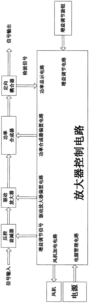
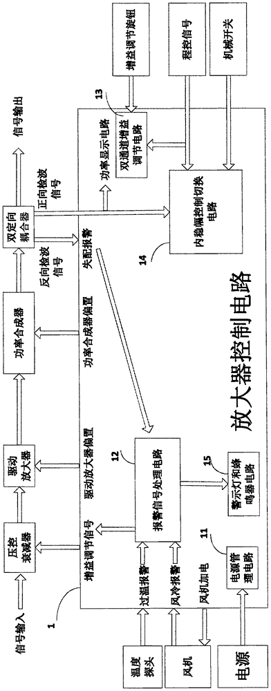
[0029] The present invention has designed a novel high-reliability multi-functional power amplifier control circuit, its principle block diagram is as follows figure 2 As shown, the power amplifier control circuit 1 mainly includes a power management circuit 11 , an alarm signal processing circuit 12 , a dual-channel gain adjustment circuit 13 and an internal amplitude stabilization control switching circuit 14 .

[0030] Among them, the power management circ...


PUM


Abstract

The invention provides a power amplifier control circuit comprising a power supply management circuit, an alarm signal processing circuit, a binary channel gain adjusting circuit, and an internal amplitude stabilizing control switching circuit; the alarm signal processing circuit can monitor amplifier work status in real time; the binary channel gain adjusting circuit can realize simulation / digit binary channel gain adjustment; in the internal amplitude stabilizing control switching circuit, a first double-pole double-throw electronic switch and a second double-pole double-throw electronic switch are controlled by a program control signal, thus switching the internal amplitude stabilizing control switching circuit between a local status and a program control status; when the power amplifier is not connected with the program control signal, a double-pole double-throw mechanical switch can be manually controlled so as to switch the power amplifier between an internal amplitude stabilizing status and an open loop status; when the program control signal is connected, the program control signal can control a third and a fourth double-pole double-throw electronic switch, thus switching the amplifier between the internal amplitude stabilizing status and the open loop status.

Description

technical field [0001] The invention relates to the microwave field, in particular to a power amplifier control circuit. Background technique [0002] The power amplifier control circuit is an important part of the microwave and millimeter wave power synthesis technology, and its index has a decisive impact on the performance of the microwave and millimeter wave power synthesis technology. With the continuous development of radar, communication, electronic countermeasures, navigation and aerospace and other application fields, higher and higher requirements are placed on the performance of power amplifiers, which not only require power amplifiers to have higher power output, but also require internal Amplitude stabilization function, that is, the output power flatness is good within a specific operating frequency range. In addition, it is also required to realize the power amplifier open loop / internal amplitude stabilization state switching function, local / program compatible...

Claims


Application Information

Patent Timeline
Patent Type & Authority Applications(China)
IPC IPC(8): H03F1/52H03G3/30G01K1/02
CPCH03F1/52H03G3/30G01K1/024
Inventor 王涛宁曰民刘金现赵浩
Owner CHINA ELECTRONIS TECH INSTR CO LTD
Why Eureka
Try Eureka