

Electrodeposited copper foil for printed wiring board and copper clad laminate using the same
A technology for printed wiring boards and copper clad laminates, applied in printed circuits, printed circuits, printed circuit manufacturing, etc., can solve the problems of reduced glossy mirror gloss, abnormal protrusions on rough surfaces, and insufficient copper cores, etc. Achieve excellent work efficiency, good machine mobility, and the effect of suppressing abnormal protrusions
- Summary
- Abstract
- Description
- Claims
- Application Information
AI Technical Summary
Problems solved by technology
Method used
Image

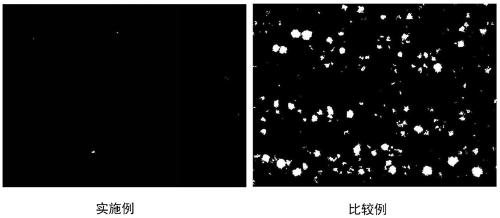
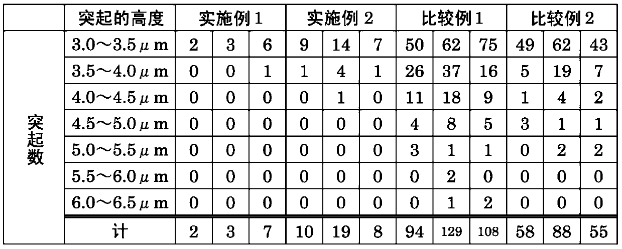
Examples
Embodiment
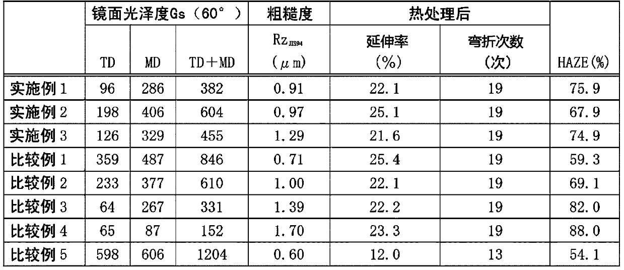
[0053] Examples of the present invention are shown below, but the present invention is not limited thereto.
[0054]
[0055] A drum-shaped rotating cathode made of titanium is used, and a cylindrical polishing wheel of No. 1500 (manufactured by Kure Grinding Wheel Co., Ltd., the same below) using silicon carbide as abrasive grains is used for finish polishing, so that the surface roughness Rz of the cathode is JIS94 1.5 μm or less.
[0056] Thereafter, an electrolytic copper foil having a thickness of 12 μm was produced under the conditions in Table 1.
[0057] [Table 1]
[0058] Copper Sulfate Pentahydrate 280g / L sulfuric acid 80g / L chlorine 40ppm Electrolyte temperature 38℃ current density 40A / dm 2
Embodiment 2 and 3
[0060] The drum-shaped rotating cathode made of titanium is finely polished using a cylindrical polishing wheel No. 1200 with silicon carbide as the abrasive grain, so that the surface roughness of the cathode is Rz JIS94 1.5 μm or less.
[0061] Thereafter, an electrolytic copper foil having a thickness of 12 μm was produced under the conditions in Table 1.
[0062]
[0063] The drum-shaped rotating cathode made of titanium is finely polished using a No. 2000 cylindrical polishing wheel with silicon carbide as the abrasive grain, so that the surface roughness of the cathode is Rz JIS94 1.5 μm or less.
[0064] Thereafter, an electrolytic copper foil having a thickness of 12 μm was produced under the conditions in Table 1.
[0065]
[0066] The drum-shaped rotating cathode made of titanium was polished with a No. 1200 cylindrical polishing wheel using silicon carbide as abrasive grains, and then polished with a No. 2000 sheet-shaped polishing pad, and finely polished, so...
PUM
| Property | Measurement | Unit |
|---|---|---|
| thickness | aaaaa | aaaaa |
| surface roughness | aaaaa | aaaaa |
| surface roughness | aaaaa | aaaaa |
Abstract
Description
Claims
Application Information