Central circulating tubular evaporator

A technology of central circulation tube and evaporator, applied in vertical tube evaporator, evaporator accessories, evaporation and other directions, can solve the problems of low heat transfer coefficient of convection boiling, reduced effective temperature difference, large solution viscosity, etc. Convective heat transfer coefficient and convective diffusivity, improving convective heat transfer coefficient, the effect of uniform concentration and viscosity distribution

Inactive Publication Date: 2016-11-09
FOSHAN UNIVERSITY
View PDF5 Cites 3 Cited by
  • Summary
  • Abstract
  • Description
  • Claims
  • Application Information

AI Technical Summary

Problems solved by technology

However, in the existing central circulation tube evaporator, due to the continuous circulation of the solution, the solution in the heating tube is always close to the concentration of the completed liquid, so the solution has a high viscosity, a high boiling point, a reduced effective temperature difference, and a low convective boiling heat transfer coefficient. fouling

Method used


Image

  • Central circulating tubular evaporator
  • Central circulating tubular evaporator
  • Central circulating tubular evaporator

Examples


Embodiment 1

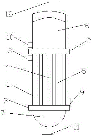
[0027] Such as figure 1 with figure 2 As shown, a central circulation tube evaporator includes a cylinder body 1, an upper tube sheet 2 and a lower tube sheet 3 welded in the cylinder body 1 and vertically connected to the cylinder body 1, and the upper tube sheet 2 and the lower tube sheet 3 There is a central circulation pipe 4 coincident with the axis of cylinder body 1 and a group of boiling pipes 5 arranged around the central circulation pipe 4. The upper tube plate 2 is connected with the upper head to form a steam chamber 6, and the lower tube plate 3 is connected with the lower seal. The head forms a lower tube box 7, and the cylinder body 1 is connected to the shell side primary steam inlet pipe 8 near the upper tube plate 2, and the other side of the cylinder body 1 opposite to the shell side primary steam inlet tube 8 is provided near the lower tube plate 3. There is a shell-side condensate outlet pipe 9, a tube-side solution inlet pipe 10 is provided on the side ...

Embodiment 2

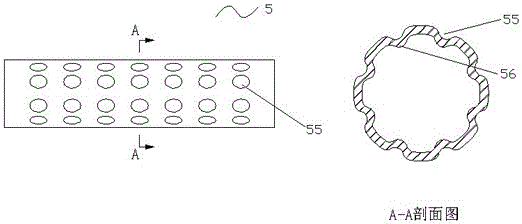
[0033] Such as figure 1 with image 3 As shown, the structure of the central circulation tube evaporator is the same as that of Embodiment 1, the difference is that: the outer surface of the boiling tube 5 is provided with 8 micro-concaves 55 along the circumference, and the micro-concaves 55 are spherically arranged on the outer surface of the boiling tube 5 The surface is equally spaced along the axial direction, and spherical protrusions 56 are formed on the inner surface of the boiling tube 5 corresponding to the micro-concave surface 55 outside the tube. The ratio of the diameter of the micro-concave surface 55 to the diameter of the boiling tube 5 is 1:10.

Embodiment 3

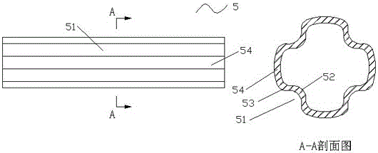
[0035] Such as figure 1 with Figure 4 As shown, the structure of the central circulation tube evaporator is the same as that of Embodiment 1, the difference is that, in order to further improve the convective heat transfer coefficient, the outer surface of the boiling tube 5 is provided with 4 grooves 51 and 4 microscopic grooves at intervals along the circumferential direction. Concave surface 55 , four slightly concave surfaces 55 are uniformly arranged on the protrusions 54 in two adjacent grooves 51 .


PUM


Abstract

The invention discloses a central circulating tubular evaporator. The central circulating tubular evaporator comprises a barrel, an upper tube plate and a lower tube plate, wherein the upper tube plate and the lower tube plate are welded into the barrel and vertically connected with the barrel, a central circulating tube and a set of boiling tubes are arranged between the upper tube plate and the lower tube plate, the axis of the central circulating tube is coincident with the axis of the barrel, the boiling tubes surround the central circulating tube, and the outer surfaces of the boiling tubes are provided with a plurality of grooves and/or tiny concave surfaces in the circumferential direction. According to the central circulating tubular evaporator, the outer surfaces of the boiling tubes are provided with the grooves and/or the tiny concave surfaces in the circumferential direction, convex ribs in the tubes stretch into the central areas of the tubes, and heat exchange of fluid in the central areas in the tubes is enhanced; tiny spherical protrusions in the tubes periodically disturb the fluid close to the walls of the tubes, under the same flow sectional area, the heat transfer area is enlarged, the heat transfer rate is increased, and scaling does not occur easily.

Description

technical field [0001] The invention relates to the technical field of heat exchange equipment, in particular to a central circulation tube evaporator. Background technique [0002] The central circulation tube evaporator is a natural circulation evaporator. It is a large-scale evaporator widely used in industrial production and has a long history, and it is still widely used in chemical industry, light industry, environmental protection and other industries. The central circulating tube evaporator is developed from the evaporators in the horizontal heating chamber and coil heating chamber. Compared with these old-fashioned evaporators, it has the advantages of good solution circulation and fast heat transfer rate. At the same time, it is compact in structure and easy to manufacture. , widely used, known as "standard evaporator". However, in the existing central circulation tube evaporator, due to the continuous circulation of the solution, the solution in the heating tube...

Claims


Application Information

Patent Timeline
Patent Type & Authority Applications(China)
IPC IPC(8): B01D1/00B01D1/12B01D1/30
CPCB01D1/00B01D1/12B01D1/30
Inventor 黄德斌黄华健
Owner FOSHAN UNIVERSITY
Why Eureka
Try Eureka