A kind of slag gasification furnace with slagging device

A technology of molten slag gasification and slag pool, applied in the field of coal gasification, can solve the problems that the slag outlet of the gasifier is easy to be blocked, affects the normal operation of the gasifier, and the slag discharge of the gasifier is not smooth. Effects of stable operation capability, integrity protection, and structural simplification

Active Publication Date: 2019-01-22
HARBIN INST OF TECH
View PDF5 Cites 0 Cited by
  • Summary
  • Abstract
  • Description
  • Claims
  • Application Information

AI Technical Summary

Problems solved by technology

[0004] The object of the present invention is to provide a slag gasifier with a slag discharge device to solve the problem that the lower slag port of the gasifier in the prior art is easy to block the slag, resulting in poor slag discharge of the gasifier and the existence of gasification due to entrained bed gas. The quenching ring and downcomer of the lower slag mouth of the gasifier are easily burned out, which affects the normal operation of the gasifier

Method used


Image

  • A kind of slag gasification furnace with slagging device
  • A kind of slag gasification furnace with slagging device
  • A kind of slag gasification furnace with slagging device

Examples


specific Embodiment approach 1

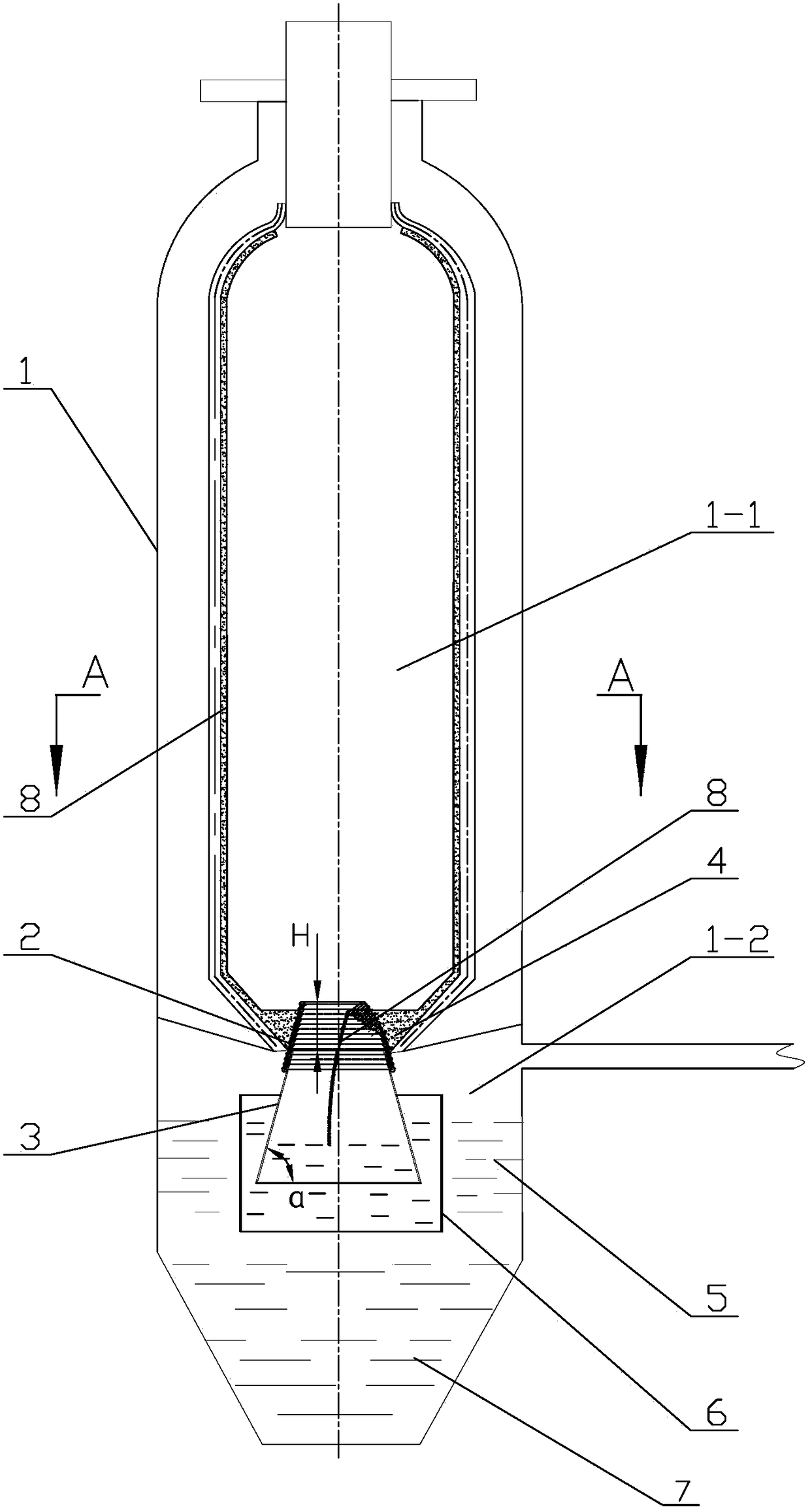
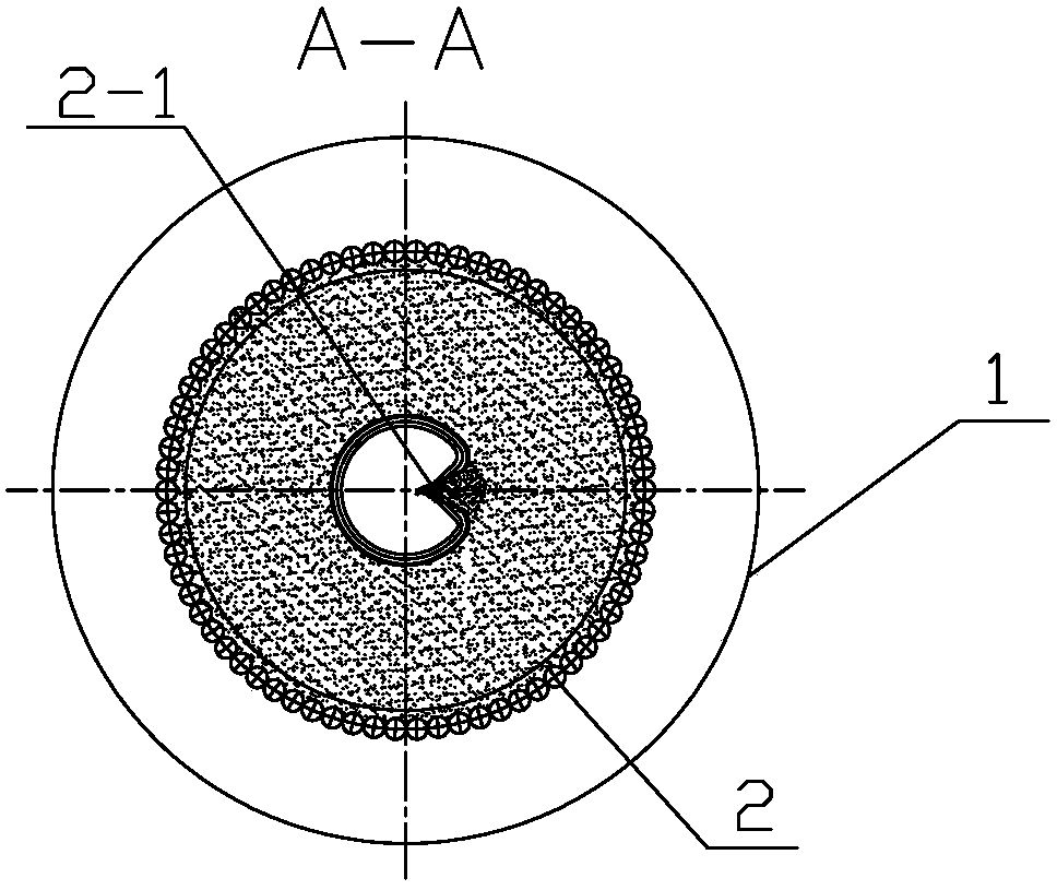
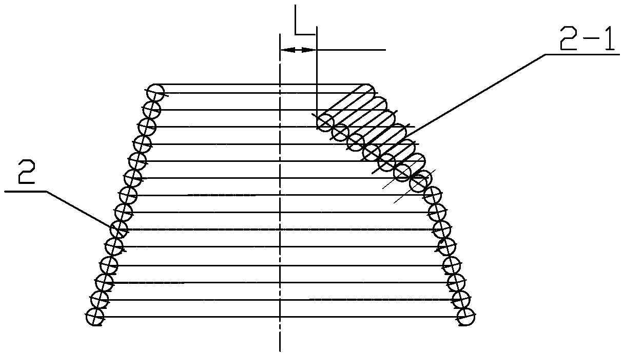
[0024] Specific implementation mode one: combine figure 1 , figure 2 , image 3 and Figure 4 This embodiment is described. This embodiment includes a slag gasifier body 1, a water-cooled coil 2 and a downcomer 3. The interior of the slag gasifier body 1 is sequentially divided into a combustion chamber 1-1 and a quenching chamber 1-1 from top to bottom. Chamber 1-2, the water-cooled coil 2 is set inside the slag gasifier body 1, the water-cooled coil 2 is a conical cylinder formed by a water-cooled pipe spiraling from top to bottom, and the water-cooled coil The top end of 2 is a small mouth end and this end is arranged in the combustion chamber 1-1, and the bottom end of the water-cooled coil 2 is a large mouth end and this end is arranged in the quenching chamber 1-2, and the combustion chamber 1-1 and the excitation chamber The cold chamber 1-2 is connected through the water cooling coil 2, the outer wall of the top of the water cooling coil 2 is processed with a gap 2...

specific Embodiment approach 2

[0029] Specific implementation mode two: combination figure 1 , figure 2 , image 3 and Figure 4 This embodiment will be described. In this embodiment, the main body 1 of the slag gasifier, the water-cooled coil 2 and the downcomer 3 are arranged coaxially. Such setting can achieve a more stable slagging effect. Other unmentioned structures and connections are the same as those in the first embodiment.

specific Embodiment approach 3

[0030] Specific implementation mode three: combination figure 1 , figure 2 , image 3 and Figure 4 Describe this embodiment, the height of the water-cooled coil 2 in this embodiment is h, the vertical distance between the top of the water-cooled coil 2 and the bottom of the combustion chamber 1-1 is H, and the H is 0.4- 0.9h. The setting relationship between H and h in this embodiment is obtained through multiple sample tests. When H is 0.4-0.9h, an annular melting zone with sufficient volume can be formed between the water-cooled coil 2 and the combustion chamber 1-1. Slag storage tank 4. Other unmentioned structures and connections are the same as those in the first or second embodiment.

[0031] Specific implementation mode four: combination figure 1 , figure 2 , image 3 and Figure 4 Describe this embodiment. In this embodiment, the gap 2-1 is a gap set toward the central axis of the water-cooled coil 2. The shape of the gap 2-1 is a built-in spout shape. The ...


PUM


Abstract

A melt-slag gasifier with slag discharging device relates to a melt-slag gasifier. In the prior art, a slag-tapping port of a gasifier is easily blocked by slags and accordingly the gasifier cannot smoothly discharge slags, and there is the problem that the gasification surface cannot normally operate because of burning loss of a quenching ring at the slag-tapping port of the entrained flow gasifier and a downcomer. The interior of the melt-slag gasifier is successively divided into a combustion chamber and a quenching chamber from top to bottom; a water cooling coil is disposed in the melt-slag gasifier body, and forms a conical barrel through coiling of a water cooling pipe from top to bottom, the top end of the water cooling coil is disposed in the combustion chamber, the bottom end of the water cooling coil is disposed in the quenching chamber, the combustion chamber and the quenching chamber are communicated through the water cooling coil, the outer wall at the top end of the water cooling coil is provided with a notch, and an annular melt-slag storage groove is formed between the outer wall of the water cooling coil and the inner wall at the bottom of the combustion chamber; and the downcomer is disposed in the quenching chamber, the upper end of the downcomer is communicated with the water cooling coil, and the lower end of the downcomer is inserted into cooling water of the quenching chamber. The device is applied to the field of coal gasification.

Description

technical field [0001] The invention relates to a molten slag gasifier, which belongs to the technical field of coal gasification. Background technique [0002] my country is rich in coal resources, which account for the main body of the energy consumption structure, but the utilization of coal at this stage has serious shortcomings such as heavy pollution and low efficiency. In recent years, the clean and efficient utilization of coal is an important direction of my country's development, and coal gasification technology is an important means to realize the clean and efficient utilization of coal. The current coal gasification technology, especially entrained bed coal gasification technology, has been widely used in industry due to its advantages of high gasification intensity, strong production capacity, and high carbon conversion rate, and has become the main development direction of coal gasification technology. [0003] The high-temperature flue gas and molten slag pro...

Claims


Application Information

Patent Timeline
Patent Type & Authority Patents(China)
IPC IPC(8): C10J3/20C10J3/34C10J3/72
CPCC10J3/20C10J3/34C10J3/72C10J2300/1628
Inventor 陈智超王浩鹏何额尔敦木图乔大成曾令艳李争起
Owner HARBIN INST OF TECH
Why Eureka
Try Eureka