A filter wall for upstream tailings pond

A technology for filter walls and tailings ponds, applied in soil protection, filling, construction, etc., can solve problems such as the rise of the infiltration line of the lower reservoir, reduce the seepage effect, and construction difficulties, so as to achieve the safety and stability of the dam body and improve the Good effect of seepage drainage and interception

Active Publication Date: 2017-12-15
武汉科技大学资产经营有限公司
View PDF1 Cites 0 Cited by
  • Summary
  • Abstract
  • Description
  • Claims
  • Application Information

AI Technical Summary

Problems solved by technology

[0005] "A reverse seepage drainage system suitable for upstream tailings ponds and upstream tailings ponds" (CN204435430U) patented technology uses a reverse seepage drainage system to drain seepage from upstream tailings ponds. The system has the following deficiencies: 1. In the early tailings discharge process, it is necessary to continuously lay seepage blind ditch in the tailings. In the later tailings discharge process, it is necessary to continuously lay aqueducts and seepage blind ditch in the tailings. The construction is more cumbersome , the construction cost of the tailings pond is not easy to control; 2. In the process of stacking the tailings in the later stage, the fine-grained tailings in the tailings water will gradually accumulate around the seepage channels of the seepage well and the reverse filter layer of the blind drainage ditch to form a slime interlayer , which reduces the seepage effect, and the tailings water clarification area is relatively high, and the tailings water seeps through the cutoff wall to the downstream direction, causing the infiltration line of the lower reservoir to rise, posing a threat to the stability of the sub-dam; 3. Seepage blind ditch , Seepage collection wells are all constructed in the tailings, the installation of pipe fittings is inconvenient, and the construction is difficult
[0006] Song Zhi compared the seepage effect of the seepage wall formed by the seepage well and the water collection pipe in the upstream tailings pond (Song Zhi. Analysis of seepage wall technology and seepage effect [J]. Hunan Nonferrous Metals, 2012, 28(1): 5-8.), proposed a seepage drainage method with a relatively good drainage effect of multi-layer water collection pipe drainage wall, but the drainage facility also has the following shortcomings: 1. Water wells, water collection pipes and plastic inserts are inconvenient to transport and install in the tailings, and construction is difficult; 2. With the height of the tailings, the infiltration line upstream of the seepage wall cannot be effectively reduced, and the infiltration line is likely to cause the upstream direction of the seepage wall The sub-dam is not stable; 3. The water collecting pipe is prone to clogging to varying degrees in the later stage of tailings discharge, which weakens the seepage drainage effect, and the tailings water seeps downstream, and the infiltration line tends to follow the sub-dam slope in the downstream direction of the seepage wall out, it is easy to cause the instability of the sub-dam body
[0007] It can be seen that although the existing upstream tailings pond drainage method can achieve better seepage drainage effect in the early stage, as the tailings continue to pile up, the fine-grained tailings in the tailings water will continue to be buried in the early stage. Sludge interlayers are formed around the seepage drainage facilities, resulting in poor seepage drainage effects of the drainage facilities

Method used


Image

  • A filter wall for upstream tailings pond
  • A filter wall for upstream tailings pond
  • A filter wall for upstream tailings pond

Examples


Embodiment 1

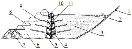
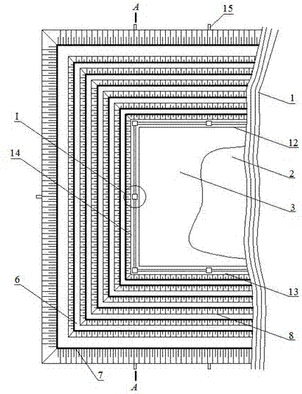
[0036] A filter wall for an upstream tailings pond. Such as figure 1 and figure 2 As shown, the filter wall is surrounded by a first filter wall 12 , a second filter wall 13 and a third filter wall 14 . The first water filter wall 12 and the second water filter wall 13 extend outwards from both sides of the hillside 1 and are respectively connected to the two ends of the third water filter wall 14. The first water filter wall 12 is connected to the third water filter The included angle between the walls 14 is 90°, and the included angle between the second filter water wall 13 and the third filter water wall 14 is 90°.

[0037] Such as figure 1 and figure 2 As shown, the filter wall and the hillside 1 form the inner reservoir 3, and the filter wall, the sub-dams 8 at various levels and the initial dam 7 constitute the outer reservoir 6.

[0038] Such as figure 1As shown, the wall cross sections of the first filter wall 12 , the second filter wall 13 and the third filter...

Embodiment 2

[0048] A filter wall for an upstream tailings pond. Except following technical parameter, all the other are with embodiment 1:

[0049] The angle between the first filter wall 12 and the third filter wall 14 is 90-120°, and the angle between the second filter wall 13 and the third filter wall 14 is 90-120°.

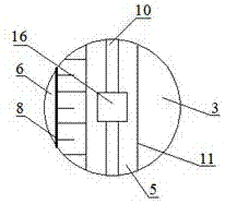
[0050] The base angle of the isosceles trapezoid is 70-80°, the top edge of the isosceles trapezoid is 4-8m, and the height of the isosceles trapezoid is 20-100m; the thickness of the concrete interlayer 10 is 0.5-1m.

[0051] The spacing of the water collection wells 16 is 20-100m.

[0052] Both sides of the concrete interlayer 10 are symmetrically provided with 5 to 10 layers of water collecting plates 4 , and the interlayer spacing of each layer of water collecting plates 4 is 5 to 10 m.

[0053] The distance between the water filter pipes 9 in the same row is 5-15m.

[0054] The lengths of the first water filter wall 12 , the second water filter wall 13 and the thi...


PUM


Abstract

The invention relates to a water filtration wall for an upstream type tailing pond. According to the technical scheme, the water filtration wall is formed by a first water filtration wall body (12), a second water filtration wall body (13) and a third water filtration wall body (14) in an enclosed mode. The first water filtration wall body (12) and the second water filtration wall body (13) extend outwards from the two sides of a mountain slope (1) correspondingly and are correspondingly connected with the two ends of the third water filtration wall body (14). The main bodies of the water filtration wall bodies have the same cross-section shape which is a constant-section isosceles trapezoid. According to each isosceles trapezoid, a concrete interlayer (10) is arranged in the middle and located at the perpendicular bisector of the top edge of the isosceles trapezoid, 4-16 layers of water collecting plates (4) are symmetrically arranged on the two sides of the concrete interlayer (10), and a row of water filtration pipes (9) is arranged above each layer of water collecting plates (4). Each concrete interlayer (10) is uniformly provided with water collecting wells (16), gravel (5) is symmetrically laid on the two sides of each concrete interlayer (10), and geotechnical cloth (11) is laid on the inclined surface of the gravel (5). The water filtration wall for the upstream type tailing pond has the advantages that the seepage drainage and stopping effects are good, cost is low, a dam body is safe and steady and construction is easy and convenient.

Description

technical field [0001] The invention belongs to the technical field of seepage drainage of upstream tailing ponds. Specifically, it relates to a filter wall used for an upstream tailings pond. technical background [0002] The tailings pond is a special site for stacking tailings by using the existing terrain to pile up a stable dam body. The dam construction methods of sub-dams at all levels can be divided into upstream type, downstream type and mid-line type. The tailings pond formed by the upstream type of sub-dams at all levels is called the upstream tailings pond. The upstream tailings pond has the advantages of small investment, Due to the advantages of simple construction technology and convenient operation and management, most mines use upstream tailings ponds. [0003] The sub-dams of all levels of upstream tailings ponds are mostly built by tailings alluvial method. For large and medium-sized tailings ponds, the height of each sub-dam along the upstream direction...

Claims


Application Information

Patent Timeline
Patent Type & Authority Patents(China)
IPC IPC(8): E02D17/18E02D3/10
CPCE02D3/10E02D17/18
Inventor 刘艳章刘永涛张奎叶义成柯丽华盛建龙王其虎陈小强潘世华邹晓甜吴恩桥王文杰叶祖洋
Owner 武汉科技大学资产经营有限公司
Why Eureka
Try Eureka