Wet type exhaust silencer
An exhaust muffler and muffler technology, applied in the direction of muffler device, exhaust device, machine/engine, etc., can solve the problems of cooling the exhaust connecting pipe after the diesel engine vortex, the noise reduction effect is not obvious, etc., and achieve the effect of noise reduction and cooling Significant, noise reduction, simple and compact effect
- Summary
- Abstract
- Description
- Claims
- Application Information
AI Technical Summary
Problems solved by technology
Method used
Image
Examples
Embodiment 1
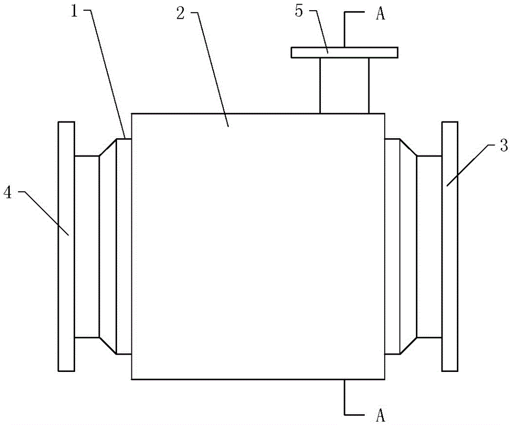
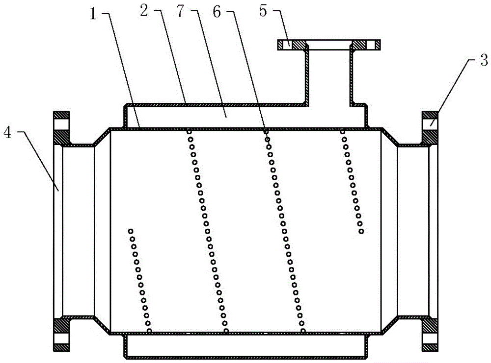
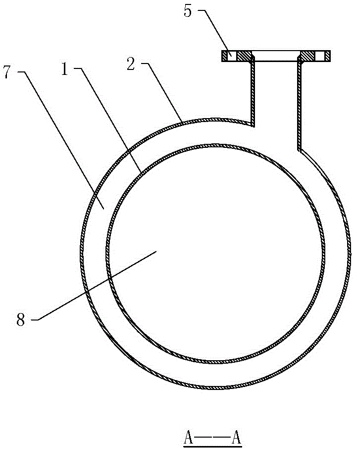
[0041] One of the embodiments of a wet exhaust muffler of the present invention, such as figure 1 , figure 2 and image 3 As shown, it includes a muffler main body 1 and a muffler shell 2. The muffler shell 2 covers the muffler main body 1 to form an annular jacket tube cavity 7. The muffler shell 2 is provided with a cooling water inlet joint 5. The muffler main body 1 is located at Water spray holes 6 are distributed in the circumferential direction of the pipe wall of the annular jacket lumen 7 .
[0042] The diameter of the tail gas passage 8 of the muffler main body 1 is larger than the diameter of the air inlet, so that the tail gas is expanded and the noise is effectively reduced. At the same time, the water spray hole 6 sprays a small water column into the exhaust passage 8 of the muffler main body 1, forming a water curtain inside the muffler main body 1, increasing the contact area and heat exchange time between the high-temperature gas and the water curtain, and ...
Embodiment 2
[0046] One of the embodiments of a wet exhaust muffler of the present invention, such asfigure 1 , figure 2 with image 3 As shown, the main technical solution of this embodiment 2 is basically the same as that of embodiment 1, and the features not explained in this embodiment 2 are explained in embodiment 1, and will not be repeated here. The difference between this embodiment and Embodiment 1 is that: the water spray holes 6 are arranged continuously to form water spray gaps. The water spray hole 6 is further deformed to be set as a continuous water spray slit, and the water spray slit can be one continuous one, or can be set as a plurality of continuous water spray slits in sections.
Embodiment 3
[0048] One of the embodiments of a wet exhaust muffler of the present invention, such as figure 1 , figure 2 with image 3 As shown, the main technical scheme of this embodiment 3 is basically the same as that of embodiment 1 or embodiment 2, and the features that are not explained in this embodiment 3 adopt the explanations in embodiment 1 or embodiment 2, and are not repeated here to repeat. The difference between Embodiment 3 and Embodiment 1 or Embodiment 2 is that the cooling water inlet joint 5 is arranged on the side close to the inlet of the exhaust pipe.
[0049] In this embodiment, the cooling water inlet joint 5 is eccentrically arranged on the muffler shell 2 . It is used to control the automatic rotation of the cooling water entering the annular jacket tube cavity 7 from the cooling water inlet joint 5, so as to improve the heat exchange efficiency.
PUM
| Property | Measurement | Unit |
|---|---|---|
| Diameter | aaaaa | aaaaa |
| Width | aaaaa | aaaaa |
Abstract
Description
Claims
Application Information
 - R&D
- Intellectual Property
- Life Sciences
- Materials
- Tech Scout
- Unparalleled Data Quality
- Higher Quality Content
- 60% Fewer Hallucinations
Browse by: Latest US Patents, China's latest patents, Technical Efficacy Thesaurus, Application Domain, Technology Topic, Popular Technical Reports.
© 2025 PatSnap. All rights reserved.Legal|Privacy policy|Modern Slavery Act Transparency Statement|Sitemap|About US| Contact US: help@patsnap.com


