Control method of composite rotor bearingless switched reluctance machine

A technology of switched reluctance motor and composite rotor, which is applied in the direction of AC motor control, control system, magnetic circuit, etc., and can solve the problems of high cost, limited output torque, and insufficient excitation

Active Publication Date: 2016-11-09
NANJING UNIV OF POSTS & TELECOMM
View PDF8 Cites 20 Cited by
  • Summary
  • Abstract
  • Description
  • Claims
  • Application Information

AI Technical Summary

Problems solved by technology

The alternate conduction control method is often used, and the number of phases of the suspension winding is the same as that of the torque winding, resulting in a complex suspension power circuit and high cost
In addition, due

Method used


Image

  • Control method of composite rotor bearingless switched reluctance machine
  • Control method of composite rotor bearingless switched reluctance machine
  • Control method of composite rotor bearingless switched reluctance machine

Examples


Embodiment Construction

[0053] The technical scheme of the control method of a composite rotor bearingless switched reluctance motor of the present invention will be described in detail below in conjunction with the accompanying drawings:

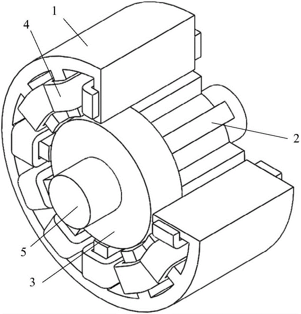
[0054] Such as figure 1 Shown is a three-dimensional structural diagram of a three-phase 12 / 8-pole compound rotor bearingless switched reluctance motor, where 1 is the stator, 2 is the salient pole rotor, 3 is the cylindrical rotor, 4 is the winding, and 5 is the shaft.

[0055] A composite rotor bearingless switched reluctance motor includes a stator, a rotor and a winding; the stator is a salient pole structure, and the number of stator teeth is 12; the rotor is composed of a cylindrical rotor and a salient pole rotor, and the cylindrical rotor is cylindrical structure, the salient pole rotor is a salient pole structure, and the number of rotor teeth is 8; the cylindrical rotor and the salient pole rotor are closely arranged in series, sleeved on the rotating sh...


PUM


Abstract

The invention discloses a control method of a composite rotor bearingless switched reluctance machine. A stator of the machine is of a salient pole structure and is provided with twelve stator teeth, each stator is only provided with a set of winding, a rotor comprises a salient pole rotor and a cylindrical rotor, the cylindrical rotor is used for generating a suspension force, and the salient pole rotor is provided with eight teeth and is used for generating a torque; in a suspension excitation section, four windings of each phase are independently controlled and are equivalent to a main winding and two suspension windings, and a calculation method of a main winding current and suspension winding currents with minimum winding copper loss is adopted; and in a torque excitation section, the four windings of each phase are jointly controlled, and the rotational speed and the torque are controlled in real time by controlling a chopping limit and a turn-off angle of a phase winding current. By the method, the torque control and the suspension force control are decoupled, coordination control is performed, the high-speed suspension property is good, the control variable is reduced, simple control and convenient implementation are achieved, and the copper loss in the suspension section is small.

Description

technical field [0001] The invention relates to a control method of a composite rotor bearingless switched reluctance motor, belonging to the technical field of control of a magnetic levitation switched reluctance motor. Background technique [0002] The bearingless switched reluctance motor is a new type of magnetic levitation motor developed in the 1990s. Since the bearingless switched reluctance motor integrates the functions of rotation and suspension, it can not only effectively solve the problems of loss and heat caused by bearing friction during high-speed operation, but also further exert the high-speed adaptability of the switched reluctance motor, thereby strengthening its Application base in high-speed fields such as aerospace, flywheel energy storage, and ships. [0003] The study found that whether the rotation and levitation functions of the bearingless switched reluctance motor can be decoupled, as well as the tracking and chopping control accuracy of the lev...

Claims


Application Information

Patent Timeline
IPC IPC(8): H02P25/08H02K16/02H02K1/14H02K1/24H02K1/22
CPCH02K1/145H02K1/22H02K1/246H02K16/02H02P25/08
Inventor 刘泽远蔡骏杨艳刘程子曹鑫邓智泉
Owner NANJING UNIV OF POSTS & TELECOMM
Why Eureka
Try Eureka