Multifunctional acoustic circuit enabling networking function and external connection audio source playing
A multi-function, power circuit technology, applied in the audio field, can solve the problems of edges and corners, not small in size, and limited sound and sound shape, and achieve the effect of reducing the cost of use, good sound quality, and improving experience.
- Summary
- Abstract
- Description
- Claims
- Application Information
AI Technical Summary
Problems solved by technology
Method used
Image
Examples
Embodiment 1
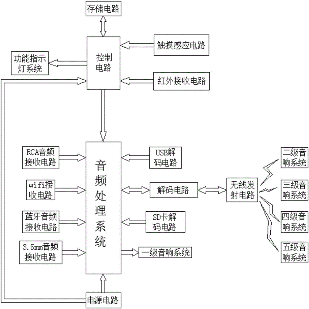
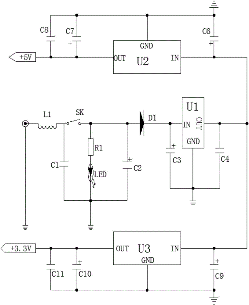
[0025] The multi-functional audio circuit with networking function and capable of playing external audio sources is designed based on wireless transmission technology, and can use wireless transmission to drive the audio system, thereby avoiding too much connection between the audio system and the audio system. The visual confusion caused by the connection between them; and the 3.3v regulated power supply and the 5v regulated power supply can be used to supply power to the control circuit system and the audio processing circuit respectively, and a three-terminal voltage regulator is used to set the conversion between voltages. It can effectively avoid affecting the operation of the entire audio circuit due to voltage instability. The entire circuit has the characteristics of simple design and good sound quality, such as figure 1 , figure 2As shown, the following structure is particularly arranged: a control circuit system, an audio processing circuit, a wireless transmitting ...
Embodiment 2
[0028] This embodiment is further optimized on the basis of the above-mentioned embodiments, and further to better realize the present invention, it can display in real time whether the input end of the 12V conversion circuit of the power supply circuit is working normally, such as figure 1 , figure 2 As shown, the following arrangement structure is specially adopted: an indicator circuit is also arranged in the power circuit, a resistor R1 and a light-emitting diode LED are arranged in the indicator circuit, the anode of the diode D1 is grounded through the resistor R1 and the light-emitting diode LED, and the light-emitting diode The cathode of the LED is grounded; a switch SK is also provided between the second end of the inductor L1 and the anode end of the diode D1.
Embodiment 3
[0030] This embodiment is further optimized on the basis of any of the above embodiments. In order to better realize the present invention, it can better achieve the purpose of filtering, and it can be set according to different needs, such as figure 1 , figure 2 As shown, the following configuration structure is adopted in particular: the capacitor C2 is an electrolytic capacitor, and the positive pole of the capacitor C2 is connected to the positive pole of the diode D1; the capacitor C3 is an electrolytic capacitor, and the positive pole of the capacitor C3 is connected to the three-terminal regulator U1 Input terminal; both the capacitor C6 and the capacitor C7 are electrolytic capacitors, and the positive terminal of the capacitor C6 is connected to the IN terminal of the three-terminal regulator U2, and the positive terminal of the capacitor C7 is connected to the OUT terminal of the three-terminal regulator U2 Both the capacitor C9 and the capacitor C10 are electrolyti...
PUM
 Abstract
Description
Claims
Application Information
 - R&D Engineer
- R&D Manager
- IP Professional
- Industry Leading Data Capabilities
- Powerful AI technology
- Patent DNA Extraction
Browse by: Latest US Patents, China's latest patents, Technical Efficacy Thesaurus, Application Domain, Technology Topic, Popular Technical Reports.
© 2024 PatSnap. All rights reserved.Legal|Privacy policy|Modern Slavery Act Transparency Statement|Sitemap|About US| Contact US: help@patsnap.com


