Control circuit provided with positive and negative wave independent dead zone control elements

A dead zone control and control circuit technology, applied in the direction of electrical components, plasma, etc., can solve the problems of signal tailing, inconsistent pulse width, large switching loss, etc., to achieve reduced switching loss, good switching signal characteristics, and high efficiency Effect

Active Publication Date: 2016-11-09
浙江赫茨电气有限公司
View PDF5 Cites 0 Cited by
  • Summary
  • Abstract
  • Description
  • Claims
  • Application Information

AI Technical Summary

Problems solved by technology

The duty time of the switching signal in the first half cycle of this circuit and the duty time of the switching signal in the second half cycle are set by a common delay circuit, which has the characteristics of simple structure, but the circuit only works when the output terminal of the oscillation gate and the delay capacitor When the positive pole is at high level at the same time, the output terminal of the first output gate can output the switching signal, only when the output terminal of the oscillation gate and the positive pole of the delay capacitor are at low level at the same time, the output terminal of the second output gate can output the switching signal, because Affected by component parameters, the charging time and discharging time of the delay capacitor will be inconsistent. Therefore, the circuit has the disadvantage that the pulse width of the positive half cycle is inconsistent with the pulse width of the negative half cycle, and there is a tailing phenomenon of the positive and negative half cycle signals, which makes the switching loss large.

Method used


Image

  • Control circuit provided with positive and negative wave independent dead zone control elements

Examples


Embodiment 1

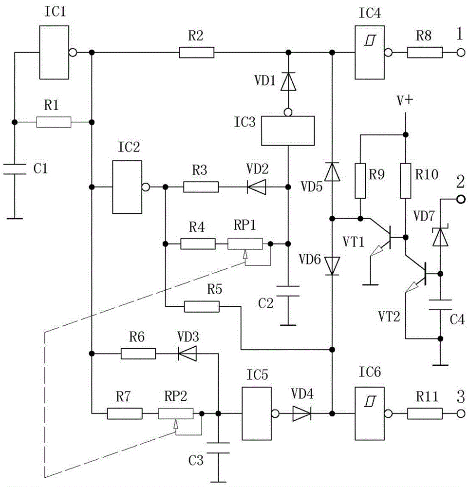
[0017] Embodiment 1 Attached figure 1 In the embodiment shown, the control circuit with positive and negative wave independent dead zone control elements is mainly composed of a NOT gate circuit, resistors, capacitors and diodes. The NOT gate circuit includes an oscillation gate (IC1), an inverting gate (IC2), a second A delay gate (IC3), a first output gate (IC4), a second delay gate (IC5) and a second output gate (IC6), the oscillation resistor (R1) is connected between the input and output of the oscillation gate (IC1) Between, there is an oscillation capacitor (C1) between the input end of the oscillation gate (IC1) and the ground wire, the output end of the oscillation gate (IC1) is connected to the first end of the first isolation resistor (R2), the inverting gate (IC2 ), the first end of the second discharge resistor (R6) and the first end of the second dead zone control resistor (R7), the second end of the first isolation resistor (R2) is connected to the first output ...


PUM


Abstract

The invention discloses a control circuit provided with positive and negative wave independent dead zone control elements, and relates to a high-frequency switching power supply circuit. The control circuit is mainly composed of a NOT gate circuit, resistors, capacitors and diodes, wherein the NOT gate circuit comprises an oscillation gate, an inverting gate, delay gates and output gates, an output end of the oscillation gate is connected to a first isolation resistor, an input end of the inverting gate, a second discharge resistor and a second dead zone control resistor, the first isolation resistor is connected to an input end of a first output gate, and an output end of the first output gate is connected to a negative half-cycle signal output end through a first output resistor; an output end of the inverting gate is connected to a first discharge resistor, a first dead zone control resistor and a second isolation resistor, the second isolation resistor is connected to an input end of a second output gate, and an output end of the second output gate is connected to a positive half-cycle signal output end through a second output resistor. According to the invention, dead zone control element of the positive half cycle and the dead zone control element of the negative half cycle are mutually independent, a trailing phenomenon of positive half-cycle signals and negative half-cycle signal in inversion is eliminated, and the efficiency of a switching power supply is enabled to be higher.

Description

technical field [0001] The invention relates to an electronic circuit, in particular to a high-frequency switching power supply control circuit. Background technique [0002] At present, plasma technology has been widely used, industrially used in plasma ignition, plasma spraying, metal smelting, plasma heating to manufacture nanomaterials, cutting, garbage incineration and waste treatment, etc. In recent years, the technology of using plasma to treat dangerous and harmful wastes and household garbage has developed rapidly. The plasma treatment method is quite different from the general incineration method. This state, accompanied by the discharge phenomenon, will generate active chemicals of excited atoms, excited molecules, dissociated atoms, free atomic groups, atomic or molecular ion groups, and their collisions with other chemical substances. In the plasma generator, the discharge effect causes the working gas molecules to lose the outer electrons and form an ion state...

Claims


Application Information

Patent Timeline
Patent Type & Authority Applications(China)
IPC IPC(8): H05H1/36
CPCH05H1/36
Inventor 周昀煜
Owner 浙江赫茨电气有限公司
Why Eureka
Try Eureka