Far-field ultrasonic probe for sonodynamic therapy
A technology of sonodynamic therapy and ultrasonic probe, applied in the field of medical instruments, can solve the problems of insufficient precise quantification and controllable effect, inability to clarify the relationship between the effect data of sonodynamic therapy, etc., and achieves high engineering application value, wide application value and high efficiency. Effect
- Summary
- Abstract
- Description
- Claims
- Application Information
AI Technical Summary
Problems solved by technology
Method used
Image
Examples
Embodiment 1
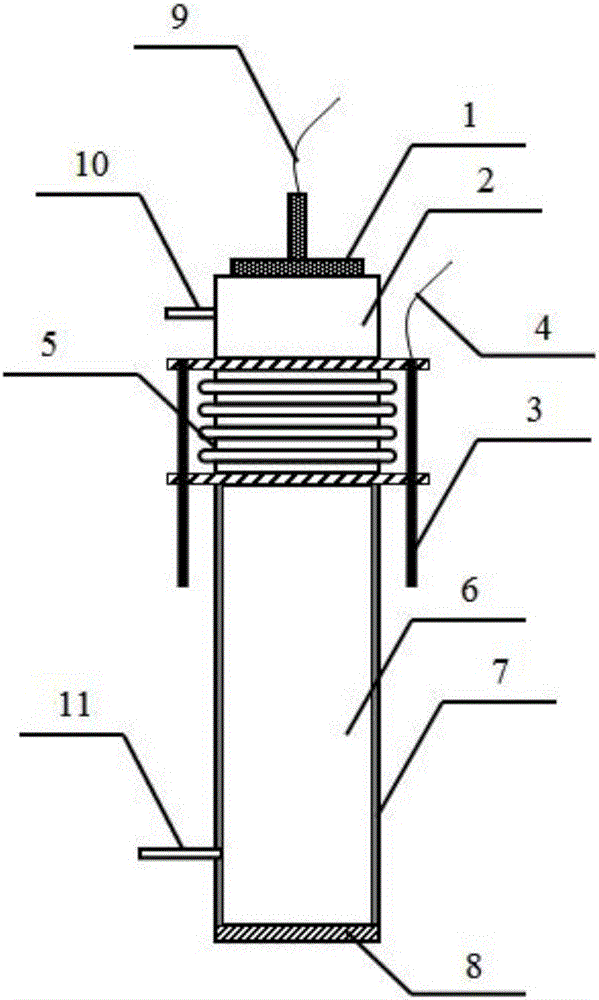
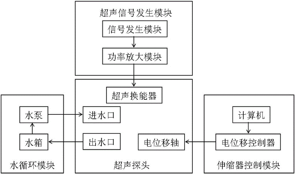
[0031] figure 1 It is a structural schematic diagram of the far-field ultrasonic probe of the present invention; as figure 1As shown, the ultrasonic probe includes an ultrasonic transducer 1, an upper ultrasonic transmission cavity 2, an electric displacement axis 3, an electric displacement axis controller connection 4, a corrugated expander 5, a lower ultrasonic transmission cavity 6, and an ultrasonic sound-absorbing layer 7. Ultrasonic coupling layer 8, ultrasonic transducer controller connection 9, water inlet 10, water outlet 11. Ultrasonic transducer 1, upper ultrasonic transmission cavity 2, electric displacement axis 3, corrugated expander 5, lower ultrasonic transmission cavity 6, ultrasonic sound-absorbing layer 7 and ultrasonic coupling layer 8; the upper ultrasonic transmission cavity 2 One end is fixedly connected with the ultrasonic transducer 1, and the other end is connected with one end of the bellows expander 5; the other end of the bellows expander 5 is co...
Embodiment 2
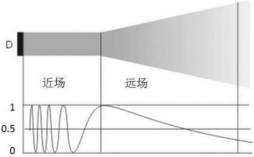
[0043] The difference between embodiment 2 and embodiment 1 lies in that the frequency used is 1.5 MHz, the diameter of the ceramic disk inside the transducer is 3.5 cm, and when the ultrasonic wave propagates in water, the length of the near-field region is about 31 cm. At this time, according to the ultrasonic frequency used by the transducer and the treatment, the length of the corrugated retractor 5 is adjusted so that the ultrasonic coupling layer 8 is located at a far-field position greater than 31 cm from the surface of the ultrasonic transducer 1 . The composition of other components and the connection mode between the components are the same as those in Embodiment 1.
Embodiment 3
[0045] The difference between embodiment 3 and embodiment 2 is that embodiment 3 provides the relationship between the ultrasonic far-field lengths of different transducer ceramic disc diameters and frequencies, as shown in Table 1.
[0046] Table 1 Ultrasonic far-field lengths of different transducer ceramic disc diameters and frequencies (unit: cm)
[0047]
[0048]
[0049] The change of sound intensity tends to be stable in the far field region, but with the increase of distance, the sound intensity gradually weakens. At this time, the length of the corrugated expander 5 can be adjusted so that the ultrasonic coupling layer 8 is taken to a place with a stronger sound field in the far field region.
[0050] The composition of other components and the connection mode between the components are the same as those in Embodiment 2.
PUM
 Abstract
Description
Claims
Application Information
 - R&D
- Intellectual Property
- Life Sciences
- Materials
- Tech Scout
- Unparalleled Data Quality
- Higher Quality Content
- 60% Fewer Hallucinations
Browse by: Latest US Patents, China's latest patents, Technical Efficacy Thesaurus, Application Domain, Technology Topic, Popular Technical Reports.
© 2025 PatSnap. All rights reserved.Legal|Privacy policy|Modern Slavery Act Transparency Statement|Sitemap|About US| Contact US: help@patsnap.com


