Vibratory feeding device for precise welding of conductive slip rings/copper rings and vibratory feeding method of vibratory feeding device

A technology of vibration feeding and conductive slip rings, which is applied to vibrating conveyors, auxiliary devices, welding equipment, etc., can solve the problems of affecting production efficiency, high labor intensity of workers, and low work efficiency, so as to improve production efficiency and product quality. Reduce the labor intensity of workers and reduce the effect of labor intensity

Active Publication Date: 2016-11-16
杭州全盛机电科技有限公司
View PDF9 Cites 8 Cited by
  • Summary
  • Abstract
  • Description
  • Claims
  • Application Information

AI Technical Summary

Problems solved by technology

[0002] At present, the welding of copper rings of conductive slip rings is manually placed at the welding position and welded one by one. The labor intensity of the workers is high

Method used


Image

  • Vibratory feeding device for precise welding of conductive slip rings/copper rings and vibratory feeding method of vibratory feeding device
  • Vibratory feeding device for precise welding of conductive slip rings/copper rings and vibratory feeding method of vibratory feeding device
  • Vibratory feeding device for precise welding of conductive slip rings/copper rings and vibratory feeding method of vibratory feeding device

Examples


Embodiment Construction

[0031] The present invention will be described in further detail below in conjunction with the accompanying drawings, but it is not intended to limit the protection scope of the present invention.

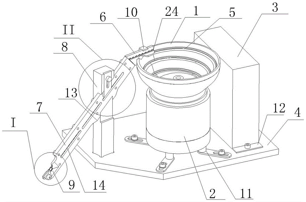
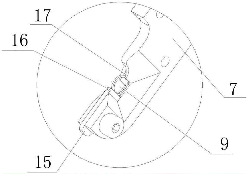
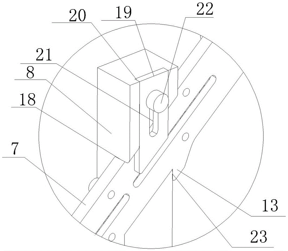
[0032] Such as Figure 1-3 As shown, a conductive slip ring copper ring precision welding vibration feeding device includes a material tray 1, a vibrator 2 that drives the vibration of the material tray 1, and a control cabinet 3 that controls the action of the vibrator 2. The inner wall of the material tray 1 is provided with a spiral Feeding track 5. The feed end of the spiral feeding track 5 is located at the bottom of the inner wall of the tray 1 , and the discharge end of the spiral feeding track 5 is located at the top of the inner wall of the tray 1 . The top of the inner wall of the material tray 1 is provided with a discharge port that matches the discharge end of the spiral feeding track 5 . The width of the spiral feeding track 5 matches the thickness of a single coppe...


PUM


Abstract

The invention discloses a vibratory feeding device for precise welding of conductive slip rings/copper rings. The vibratory feeding device comprises a material tray, a vibrator and a control cabinet, wherein a spiral loading rail is arranged on the inner wall of the material tray; the feeding end of the spiral loading rail is positioned at the bottom of the inner wall of the material tray; the discharging end of the spiral loading rail is positioned at the top of the inner wall of the material tray; a discharging port matched with the discharging end of the spiral loading rail is arranged at the top of the inner wall of the material tray; the width of the spiral loading rail is greater than the thickness of a single copper ring and less than the total thickness of two copper rings; the depth of the spiral loading rail is greater than the diameter of a one-third part of a copper ring; an inclined-downward conveying guide rail is connected onto the discharging port; a welding port is arranged at the bottom of the conveying guide rail; a welding positioning block is arranged below the welding port; a guide rail groove is formed in the conveying guide rail; and the width of the guide rail groove is matched with the thickness of a single copper ring. By adoption of the vibratory feeding device disclosed by the invention, the welding efficiency is improved and the labor intensity of workers is reduced; and the product welding quality is improved, thereby improving the production efficiency and the product quality.

Description

technical field [0001] The invention belongs to the field of precision manufacturing and processing of conductive slip rings, in particular to a vibration feeding device for precise welding of copper rings of conductive slip rings and a vibration feeding method thereof. Background technique [0002] At present, the welding of copper rings of conductive slip rings is manually placed in the welding position and welded one by one. The labor intensity of the workers is high and the work efficiency is low; Dirt such as tin slag and solder paste is easy to adhere to the copper ring; not only affects production efficiency, but also affects product quality. Contents of the invention [0003] In order to solve the defects and deficiencies in the above-mentioned prior art, the present invention provides a welding method that can improve welding efficiency, reduce labor intensity of workers, and has accurate welding positioning, can reduce solder joints, and prevent solder produced d...

Claims


Application Information

Patent Timeline
IPC IPC(8): B65G27/02B65G27/24B65G11/02B65G11/18B23K37/00
CPCB23K37/00B65G11/023B65G11/183B65G27/02B65G27/24
Inventor 李冰刘益清王笏玺
Owner 杭州全盛机电科技有限公司
Why Eureka
Try Eureka