
Electric-field-assisted ceramic low temperature rapid sintering device

An electric field assisted, ceramic technology, applied in the direction of furnace control device, electric furnace heating, charge composition/state, etc., can solve the problems of slow heating rate, inconvenient popularization, inconvenient operation, etc., and meet the requirements of reducing energy consumption and equipment, simple structure , Ease of use

Active Publication Date: 2016-11-16
SOUTHWEST JIAOTONG UNIV
View PDF4 Cites 6 Cited by
  • Summary
  • Abstract
  • Description
  • Claims
  • Application Information

AI Technical Summary

Problems solved by technology

[0002] Ceramics have superior mechanical, electrical, optical, acoustic, magnetic and other properties, and have attracted much attention in industrial applications, and their scope of use is also expanding; sintering is an indispensable process for the densification of ceramics, which consumes a large amount of At the same time, it will cause a series of environmental problems; in response to the call for energy conservation and environmental protection, researchers continue to develop new sintering technologies; such as microwave sintering, hot isostatic pressing sintering, spark plasma sintering, etc.; these sintering methods not only save Energy, also improves the performance of materials, and contributes to the wide application of materials; In 2010, Rishi Raj proposed a new ceramic sintering method - flash firing; this sintering method is assisted by an electric field, ceramic materials in a few seconds The densification can be realized within a short period of time, and the furnace temperature of sintering is significantly lower than other sintering methods; the existing flash firing devices have the following problems: first, the heating equipment is relatively expensive and not easy to popularize; second, the sintering is in a closed furnace body It is not convenient for in-situ real-time observation; third, the existing flash burning device is relatively complicated and inconvenient to operate; fourth, the heating rate is relatively slow, which is not convenient for rapid chemical industrial production; fifth, the previous flash burning device can only Measure the temperature change of a point during the flash burning process, but cannot measure the local or overall temperature distribution of the sample

Method used


Image

  • Electric-field-assisted ceramic low temperature rapid sintering device

Examples


Embodiment 1

[0031] Adopt the device of the present invention to sinter La 0.6 Sr 0.4 co 0.2 Fe 0.8 o 3 The specific steps of ceramics are as follows:

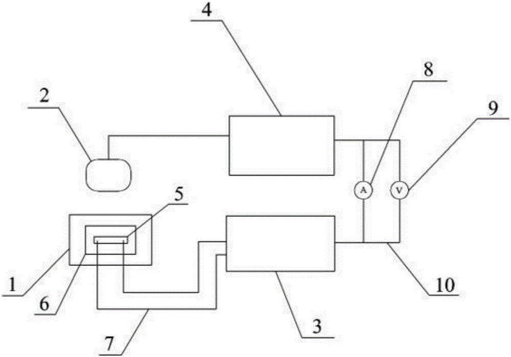
[0032] 1) Connect the two ends of the strip sample 5 to the positive and negative poles of the DC power supply 3 through the superalloy wire 7, and then place the sample 5 flat on the 99% aluminum oxide sheet on the surface of the heating plate 6;

[0033] 2) Set heating stage 1 to 300 o C, start to heat up, after reaching the set temperature, keep warm for 30min, so that the temperature of sample 5 and the surface temperature of heating platform 1 reach equilibrium;

[0034] 3) When the heating platform 1 is keeping warm, set the voltage to 30V and the current to 7.2A;

[0035] 4) Connect the infrared camera 2, voltmeter 9, ammeter 8 and data acquisition device 4 to collect temperature, line shrinkage, voltage and current data in real time;

[0036] 5) After 30 minutes of heat preservation, turn on the DC power supply 3, and after ...

Embodiment 2

[0038] Adopt the device of the present invention to sinter La 0.6 Sr 0.4 co 0.2 Fe 0.8 o 3 The specific steps of ceramics are as follows:

[0039] 1) Connect the two ends of the strip sample 5 to the positive and negative poles of the DC power supply 3 through the superalloy wire 7, and then place the sample 5 flat on the 99% aluminum oxide sheet on the surface of the heating plate 6;

[0040] 2) Set heating stage 1 to 200 o C, start to heat up, after reaching the set temperature, keep warm for 30min, so that the temperature of sample 5 and the surface temperature of heating platform 1 reach equilibrium;

[0041] 3) When the heating platform 1 is keeping warm, set the voltage to 60V and the current to 7.2A;

[0042] 4) Connect the infrared camera 2, voltmeter 9, ammeter 8 and data acquisition device 4 to collect temperature, line shrinkage, voltage and current data in real time;

[0043] 5) After 30 minutes of heat preservation, turn on the DC power supply 3, and after ...

Embodiment 3

[0045] Adopt the device of the present invention to sinter Co 2 MnO 4 The specific steps of ceramics are as follows:

[0046] 1) Connect the two ends of the strip sample 5 to the positive and negative poles of the DC power supply 3 through the superalloy wire 7, and then place the sample 5 flat on the 99% aluminum oxide sheet on the surface of the heating plate 6;

[0047] 2) Set heating stage 1 to 300 o C, start to heat up, after reaching the set temperature, keep warm for 30min, so that the temperature of sample 5 and the surface temperature of heating platform 1 reach equilibrium;

[0048] 3) When the heating platform 1 is keeping warm, set the voltage to 50V and the current to 10A;

[0049] 4) Connect the infrared camera 2, voltmeter 9, ammeter 8 and data acquisition device 4 to collect temperature, line shrinkage, voltage and current data in real time;

[0050]5) After 30 minutes of heat preservation, turn on the DC power supply 3, and after the flash burning of the s...


PUM


Abstract

The invention discloses an electric-field-assisted ceramic low temperature rapid sintering device. The rapid sintering device comprises a heating plate, a direct current power supply, an infrared camera and a data acquisition device, wherein the heating plate is used for placing and heating a sample, the two ends of the sample are respectively connected with an anode and a cathode of the direct current power supply; the infrared camera is arranged at a corresponding position of the heating plate, and the infrared camera is connected with the data acquisition device. The rapid sintering device disclosed by the invention has the advantages that heat energy is supplied to ceramic by virtue of the heating plate, and low temperature rapid sintering of a ceramic material is realized under the assistant action of a direct current electric field; and in-situ observation of temperature variation and linear contraction of the sample in each stage during flash sintering can be realized by virtue of the infrared camera and the data acquisition device, and energy consumption and requirement on equipment are effectively reduced.

Description

technical field [0001] The invention relates to a low-temperature fast-burning device for ceramics, in particular to an electric-field-assisted low-temperature fast-burning device for ceramics. Background technique [0002] Ceramics have superior mechanical, electrical, optical, acoustic, magnetic and other properties, and have attracted much attention in industrial applications, and their scope of use is also expanding; sintering is an indispensable process for the densification of ceramics, which consumes a large amount of At the same time, it will cause a series of environmental problems; in response to the call for energy conservation and environmental protection, researchers continue to develop new sintering technologies; such as microwave sintering, hot isostatic pressing sintering, spark plasma sintering, etc.; these sintering methods not only save Energy, also improves the performance of materials, and contributes to the wide application of materials; In 2010, Rishi ...

Claims


Application Information

Patent Timeline
IPC IPC(8): C04B35/26C04B35/01C04B35/64F27B21/02F27D11/02F27D19/00
CPCC04B35/01C04B35/2633C04B35/2641C04B35/2666C04B35/64C04B2235/3227C04B2235/3268C04B2235/3275C04B2235/6562F27B21/02F27D11/02F27D19/00F27D2019/0003F27D2019/0093F27M2001/035F27M2003/04
Inventor 刘金铃王一光刘佃光高燕安立楠
Owner SOUTHWEST JIAOTONG UNIV
Learn More