Device for sintering transparent ceramics by induction heating

A technology of transparent ceramics and induction heating, applied in lighting and heating equipment, muffle furnaces, furnaces, etc., can solve the problems of brittleness, high power consumption, and high sintering costs in vacuum tungsten wire sintering furnaces

Active Publication Date: 2009-10-07
SHANGHAI INST OF OPTICS & FINE MECHANICS CHINESE ACAD OF SCI
View PDF0 Cites 12 Cited by
  • Summary
  • Abstract
  • Description
  • Claims
  • Application Information

AI Technical Summary

Problems solved by technology

But its disadvantage is that the electrothermal conversion efficiency of tungsten wire heating is relatively low, and the power consumption is large, and the tungsten wire cage is easy to volatilize and become brittle during high-temperature sintering, and the heating element

Method used


Image

  • Device for sintering transparent ceramics by induction heating
  • Device for sintering transparent ceramics by induction heating
  • Device for sintering transparent ceramics by induction heating

Examples


Embodiment 1

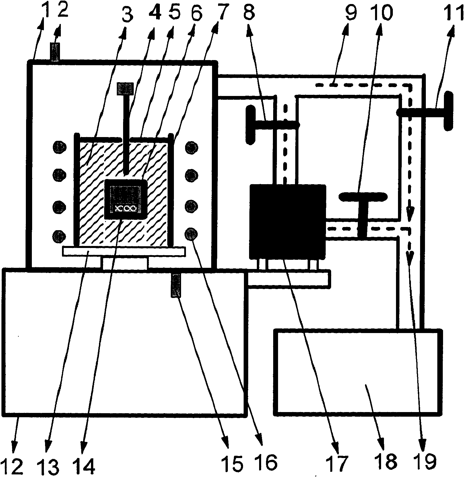
[0023] Place the Nd:YAG ceramic body to be sintered in a covered tungsten crucible 6 (as a heating element for induction heating) and then embed it in zirconia heat insulating sand 3. The tungsten crucible 6 should be at the center of the induction coil to ensure For the uniformity of temperature field, cover the quartz glass cover 5 above the zirconia sand 3, and place the end of the thermocouple 4 for temperature measurement close to the outer wall of the tungsten crucible (6).

[0024] Close the furnace door and turn on the circulating cooling water.

[0025] Turn on the mechanical pump 18, open the third baffle valve 11 to evacuate the furnace chamber through the bypass gas path 9.

[0026] When the air pressure in the furnace is ≤10Pa, open the second baffle valve 10, turn on the power switch of the molecular pump, and start the molecular pump 17. When the molecular pump reaches the rated operating frequency, the third damper valve 11 is closed, the first damper valve 8 ...

Embodiment 2

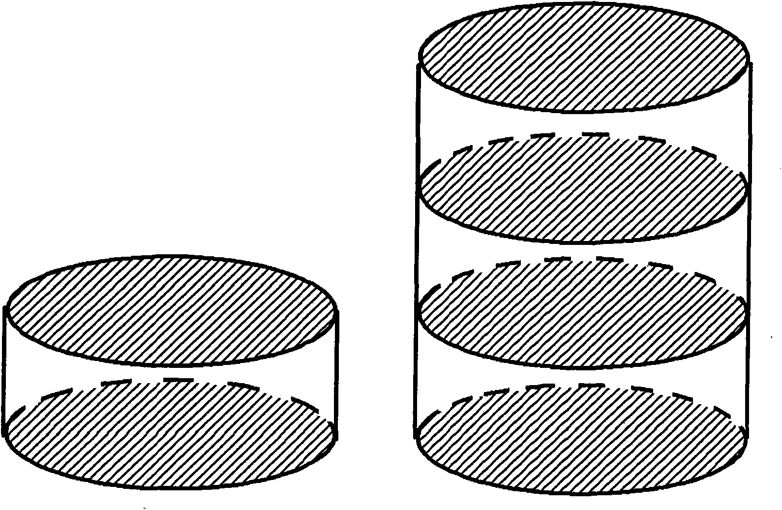
[0033] The multi-block Yb:YAG ceramic body to be sintered is placed in an iridium crucible or a plurality of stacked iridium buckets 6 as a heating element for induction heating, such as figure 2 As shown, it is embedded in the zirconia insulating sand 3; the iridium crucible or the iridium barrel 6 should be placed in the center of the induction coil to ensure the uniformity of the temperature field; the quartz glass cover 5 is covered above the zirconia sand 3; the thermocouple 4. One end of the temperature measurement is close to the outer wall of the iridium barrel 6 .

[0034] Close the furnace door and turn on the circulating cooling water.

[0035] Turn on the mechanical pump 18, open the third baffle valve 11 to evacuate the furnace chamber through the bypass gas path 9.

[0036] When the air pressure in the furnace is ≤10Pa, open the second baffle valve 10, turn on the power switch of the molecular pump, and start the molecular pump 17. When the molecular pump reac...

Embodiment 3

[0041] The Yb:Y to be sintered 2 o 3The ceramic body is placed in the graphite crucible 6 (as a heating element for induction heating) and then embedded in the porous graphite 3 (as a thermal insulation material); the graphite crucible 6 should be placed at the center of the induction coil to ensure the uniformity of the temperature field; The top of the graphite 3 is covered with a quartz glass cover 5; the temperature measuring end of the thermocouple 4 is placed close to the outer wall of the graphite crucible 6 .

[0042] Close the furnace door and turn on the circulating cooling water.

[0043] Turn on the mechanical pump 18, open the third baffle valve 11 to evacuate the furnace chamber through the bypass gas path 9.

[0044] When the air pressure in the furnace is ≤10Pa, open the second baffle valve 10, turn on the power switch of the molecular pump, and start the molecular pump 17. When the molecular pump reaches the rated operating frequency, the third damper valve...


PUM


Abstract

A device for sintering transparent ceramics by induction heating comprises a double-layer stainless steel furnace mantle with an intermediate course where cooling water can pass and a bracket supporting the furnace mantle, wherein the upper and lower walls of the furnace mantle are provided with gas ports used when atmosphere sintering, a tray is installed at the center of the bottom of the internal wall of the furnace mantle, a quartz barrel is disposed on the tray, a ceramic sample to be sintered is disposed in a heating element, and the heating element is embedded in a heat insulating material inside the quartz barrel; the quartz barrel is covered with a quartz glass cover with a round hole at the center; an induction coil is installed outside the quartz barrel; one end of a tungsten-rhenium thermoelectric couple is penetrated into the quartz barrel passing through the round hole of the quartz glass cover and is tightly close to the external wall of the heating element; a main gas path is formed by a first baffle valve, a molecular pump, a second baffle valve and a mechanical pump connected gradually at the pumping hole of the upper side of the furnace mantle via pipelines, and pipelines directly communicated with the main gas path between the furnace mantle and the first baffle valve through the third baffle vale by the mechanical pump through the pipelines are gas bypasses.

Description

technical field [0001] The invention relates to transparent ceramics, in particular to a device for sintering transparent ceramics by induction heating. Background technique [0002] In 1959, General Electric Coble RL prepared the first Al 2 o 3 Transparent ceramics break the traditional concept of "ceramic opacity", greatly promote the development and application of ceramic sintering theory, expand the application range of ceramic materials, and open up new ways for the development and application of new high-performance optical materials. Transparent ceramics not only have excellent light transmission, but also have high strength, high hardness, corrosion resistance, high temperature resistance and other properties, which are far superior to general optical materials. Moreover, it has advantages in terms of preparation cost, size (compared to single crystal), optical functional effect, mechanical properties and thermal properties (compared to glass), especially the desig...

Claims


Application Information

Patent Timeline
IPC IPC(8): F27B5/04F27B5/06F27B5/14F27B5/16C04B35/64C04B35/10C04B35/505
Inventor 周圣明林辉
Owner SHANGHAI INST OF OPTICS & FINE MECHANICS CHINESE ACAD OF SCI
Why Eureka
Try Eureka