Control system and method for cold energy utilization in LNG gasification process

A control method and control system technology, applied in the field of LNG cold energy utilization, can solve problems such as impossible dispersion, complex control of LNG gasification cold energy utilization, and influence on LNG cold energy utilization, so as to achieve low cooling range and avoid untimely Control and reduce the effect of equipment

Active Publication Date: 2016-11-16
CHINA TIANCHEN ENG +1
View PDF6 Cites 4 Cited by
  • Summary
  • Abstract
  • Description
  • Claims
  • Application Information

AI Technical Summary

Problems solved by technology

This creates a key issue that affects the utilization of LNG cold energy: factors such as safety and load regulation determine that the LNG gasification operation must be absolutely controlled by the receiving station, and it is impossible to distribute it to long-distance (> 4km) and multiple cold energy users.
[0006] The amount of LNG gasification is regulated by the receiving station. The temperature after LNG gasification must meet the needs of natural gas users. After the heating medium cools down, it must also meet the temperature requirements of cold energy users for the carrier refrigerant. Therefore, LNG gasification cooling The control of energy utilization is more complex

Method used


Image

  • Control system and method for cold energy utilization in LNG gasification process
  • Control system and method for cold energy utilization in LNG gasification process
  • Control system and method for cold energy utilization in LNG gasification process

Examples


Embodiment 1

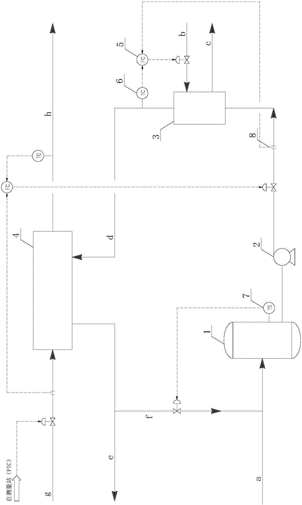
[0055] Take a gasification station with an LNG gasification capacity of 300t / h as an example. The gasification station gasifies -145°C natural gas and heats it up to 2°C, and then merges it into the municipal gas pipeline network. The brine is transported to the downstream cold energy user. The temperature requirement of the brine is -35°C. After releasing the cold energy, the brine returns to a temperature of -5°C. After heating, it enters the LNG vaporizer 4 at a temperature of 10°C. The secondary refrigerant is 30% calcium chloride solution. Sea water temperature is 15°C.

[0056] The brine is returned from the cold energy user to the brine storage tank 1, and the natural gas temperature at the natural gas outlet of the LNG vaporizer 4 is interlocked with the regulating valve at the outlet of the brine delivery pump 2 to control the calcium chloride solution entering the LNG gasification The flow rate of device 4 is 1703t / h.

[0057] Calcium chloride solution at a temper...

Embodiment 2

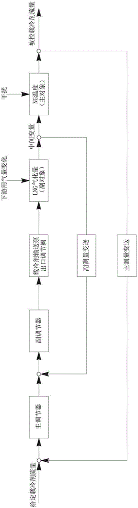
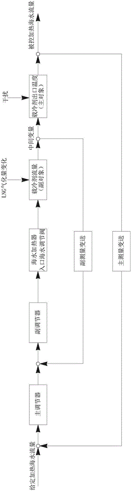
[0061] On the basis of the working conditions of Example 1, the gasification capacity of LNG is adjusted to 200t / h after the demand of natural gas users decreases. When the flow rate of the brine entering the LNG vaporizer 4 is not adjusted, the temperature of the natural gas at the outlet of the LNG vaporizer 4 rises. If a single-loop interlock control is used, the response is slow and the fluctuation is large. The temperature at which LNG enters the LNG gasifier 4 is fixed to the outlet temperature of natural gas and the temperature of the brine, and the flow of brine is proportional to the flow of natural gas, and the cascade control system provided in the present invention can be used. When the natural gas flow rate at the inlet of the LNG gasifier 4 changes to 200t / h, the interlocking (secondary circuit) between the LNG inlet flow rate and the brine delivery pump 2 outlet flow rate will adjust the brine flow rate to 1135t / h, and then the natural gas outlet temperature will...

Embodiment 3

[0064] On the basis of the working conditions of Example 1, the demand of natural gas users decreases, and the gasification capacity of LNG is adjusted to 100t / h. When the cold energy provided by the refrigerant cannot meet the cooling demand, the cold energy user decides to use the backup electric compression refrigeration system, the refrigerant storage system and the ice storage system for peak regulation.

[0065] Calcium chloride solution returns to the refrigerant storage tank 1 after long-distance transportation and the temperature rises to 12°C. The temperature in the storage tank is interlocked to open the refrigerant return line valve to control the temperature in the storage tank to 10°C. The temperature of the natural gas outlet where the calcium chloride solution enters the LNG vaporizer 4 is interlocked with the outlet regulating valve of the brine transfer pump 2 to control the flow rate of the calcium chloride solution into the LNG vaporizer 4 to be 569 t / h. Th...


PUM


Abstract

The invention provides a control system and method for cold energy utilization in an LNG gasification process. The control system comprises a coolant storage tank, a coolant conveying pump, a seawater heater and an LNG gasifier. LNG is gasified through heat exchange of the LNG gasifier and coolant; the gasified natural gas is conveyed to downstream natural gas users; the coolant after heat exchange is conveyed to cool energy users for cooling; the coolant after being heated is conveyed to the coolant storage tank; and after being discharged from the coolant storage tank, the coolant is conveyed to the seawater heater through the coolant conveying pump, and the coolant enters the LNG gasifier after reaching the specified temperature. The control system for cold energy utilization in the LNG gasification process adopts cascade control, so that the phenomenon that the temperature of the natural gas can not be controlled timely due to flow variation of an LNG inlet is avoided; and the process of heating the coolant by seawater also adopts cascade control, so that the phenomenon that the temperature of a coolant outlet can not be controlled timely due to flow variation of a coolant inlet is avoided.

Description

technical field [0001] The invention belongs to the field of cold energy utilization of LNG, and in particular relates to a control system and a control method for utilization of cold energy in an LNG gasification process. Background technique [0002] Liquefied natural gas (LNG) is a liquid mixture formed by dehydration, deacidification and low-temperature liquefaction of natural gas. The volume of liquefied natural gas is about 1 / 625 of the equivalent gas form. Natural gas (NG) is becoming more and more popular as a clean and efficient energy source. LNG is listed as the preferred fuel in many places, and the proportion of natural gas in energy supply is increasing rapidly. Each ton of LNG releases about 763 megajoules (equivalent to 212kW·h) of cold energy during the gasification process under 10MPa pressure and isobaric heating to 5°C. The full and effective use of this cold energy is conducive to improving resource utilization and creating a greater economy. benefit. ...

Claims


Application Information

Patent Timeline
Patent Type & Authority Applications(China)
IPC IPC(8): F17C7/04F17C13/02F17C13/04F17C13/00F28D21/00
CPCF17C7/04F17C13/00F17C13/02F17C13/026F17C13/04F17C2221/033F17C2227/0309F28D21/00
Inventor 王屹亮罗勇强李林孔坤瑞
Owner CHINA TIANCHEN ENG
Why Eureka
Try Eureka