Field distribution teat system applied to gyrotron traveling wave tube coupling structure and test method thereof

A technology of coupling structure and testing system, applied in the direction of electrostatic field measurement, electromagnetic field characteristics, etc., can solve the problems that restrict the application of the coupling structure of the cyclotron traveling wave tube and do not consider it

Active Publication Date: 2016-11-16
INST OF APPLIED ELECTRONICS CHINA ACAD OF ENG PHYSICS
View PDF11 Cites 1 Cited by
  • Summary
  • Abstract
  • Description
  • Claims
  • Application Information

AI Technical Summary

Problems solved by technology

However, this article only briefly introduces the near-field test and method of the antenna, without considering the influence of the near-field measurement of the antenna on the field distribution under the condition of short distance after high frequency, and does not consider the condition of high mode, for Field distribution measurement of small-sized coupling structures to be tested, and only t...

Method used


Image

  • Field distribution teat system applied to gyrotron traveling wave tube coupling structure and test method thereof
  • Field distribution teat system applied to gyrotron traveling wave tube coupling structure and test method thereof
  • Field distribution teat system applied to gyrotron traveling wave tube coupling structure and test method thereof

Examples


Embodiment Construction

[0030] The present invention will be further described in detail below in conjunction with the accompanying drawings, so that those skilled in the art can implement it with reference to the description.

[0031] It should be understood that terms such as "having", "comprising" and "including" as used herein do not entail the presence or addition of one or more other elements or combinations thereof.

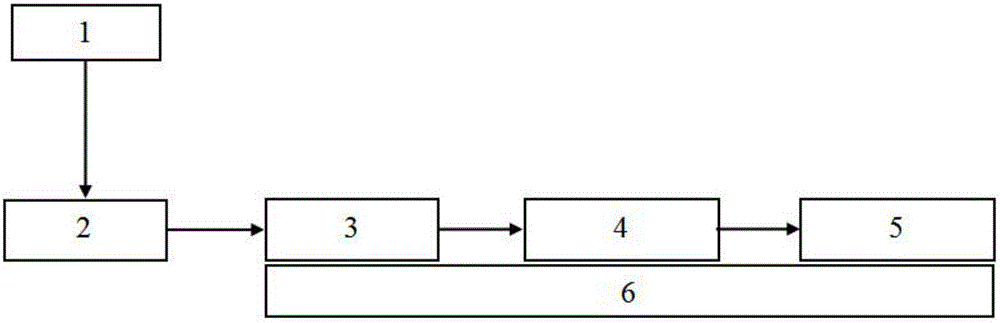
[0032] Figure 1~4 A field distribution test system for a gyrotraveling wave tube coupling structure is shown, including:

[0033] A signal source 1 for transmitting microwave signals;

[0034] And the gyrotron traveling wave tube coupling structure 2 to be tested, the waveguide probe 3, the standard WR6 waveguide 4 and the power meter 5 are sequentially arranged in the microwave signal emission direction of the signal source 1;

[0035] Among them, the waveguide probe 3, the standard WR6 waveguide 4 and the power meter 5 are placed on the three-dimensional adjustment platform ...


PUM


Abstract

The invention provides a field distribution teat system applied to a gyrotron traveling wave tube coupling structure and a test method thereof. The teat system comprises a signal source, a gyrotron traveling wave tube coupling structure to be tested, a waveguide probe and a standard WR6 waveguide and power meter, wherein the gyrotron traveling wave tube coupling structure to be tested, the waveguide probe and the standard WR6 waveguide and power meter are successively arranged in the microwave signal emission direction of the signal source. The waveguide probe and the standard WR6 waveguide and power meter are placed on a three-dimensional adjustment platform. The three-dimensional adjustment platform is adjusted to adjust a power value. One-to-one corresponding processing is carried out on the power value and the position information of the three-dimensional adjustment platform to acquire the field distribution diagram of the gyrotron traveling wave tube coupling structure. According to the invention, the field distribution of the gyrotron traveling wave tube coupling structure can be measured in the frequency range of 110GHz to 170GHz; coupling structures can be selected to satisfy the field distribution test requirement of the gyrotron traveling wave tube coupling structure; and the method is applied in the development of D-band gyrotron traveling wave tube products, has a strong practical application value, and lays a foundation for the application of terahertz products.

Description

technical field [0001] The invention relates to the technical field of microwave electric vacuum devices, in particular to a field distribution test system and a test method for a coupling structure of a cyclotron traveling wave tube. Background technique [0002] The cyclotron traveling wave tube is an electric vacuum device that amplifies the input microwave signal. It has the characteristics of high power, wide bandwidth and high gain. It has been widely used in the fields of electronic countermeasures, radar systems and high-speed wireless communications. The cyclotron traveling wave tube has become one of the promising microelectrical vacuum devices in the frequency band above 100 GHz due to its high-frequency structure with all-metal structure, fewer competing modes, and large power capacity. [0003] The high-gain amplifying device of the gyrotraveling wave tube has high requirements on the input and output coupling structure due to the performance requirements of pow...

Claims


Application Information

Patent Timeline
IPC IPC(8): G01R29/14G01R29/08
CPCG01R29/08G01R29/14
Inventor 蒋艺雷文强胡鹏胡林林孙迪敏周泉丰黄银虎宋睿阎磊曾造金卓婷婷马国武陈洪斌
Owner INST OF APPLIED ELECTRONICS CHINA ACAD OF ENG PHYSICS
Why Eureka
Try Eureka