
Photoelectric composite cable for aerostat

A photoelectric composite and aerostat technology, which is applied in the direction of communication cables, cables, circuits, etc., can solve the problems of easy breakage, low mechanical strength, and affecting the safety of cable cores.

Active Publication Date: 2012-07-18
8TH RES INST OF CETC
View PDF0 Cites 5 Cited by
  • Summary
  • Abstract
  • Description
  • Claims
  • Application Information

AI Technical Summary

Problems solved by technology

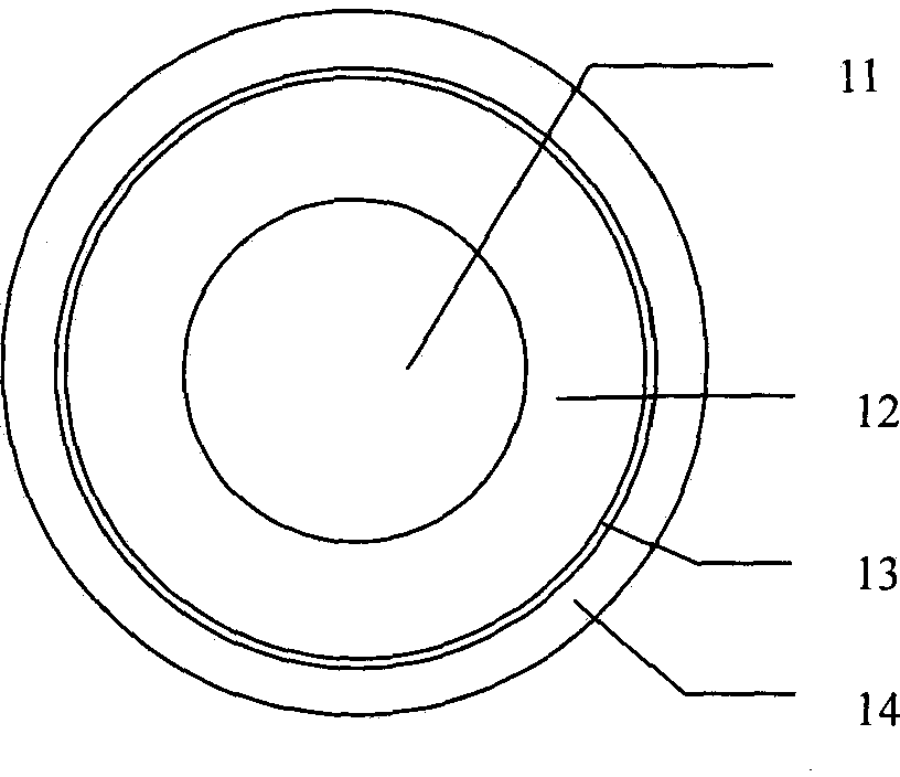
Using such a photoelectric composite cable structure scheme, at first, the polyester tape is separated between the outer sheath 14 and the lightning-discharge wire 13, and the integrity of the product is damaged. When the outer sheath 14 is subjected to a huge working pressure or tension, due to its It is not supported by other parts of the cable, so it is easy to break; secondly, the lightning discharge wire 13 is unidirectionally twisted outside the non-metallic reinforcement 12, and its tensile strength is not strong, and it is easy to break when it is subjected to a strong external force
According to experimental observations, after about 100 times of retracting and unwinding, the outer diameter of this type of power cable shrinks, and problems such as breakage of the lightning discharge wire and tearing of the outer sheath occur.
In addition to the above-mentioned problem of low mechanical strength, this type of power cable has no effective barrier between the lightning discharge wire 13 and the non-metallic external reinforcement 12, so when it is struck by a strong lightning, the strong current passing through the lightning discharge wire 13 It may also damage the non-metallic outer reinforcement 12, thereby affecting the use safety of the cable core

Method used


Image

  • Photoelectric composite cable for aerostat
  • Photoelectric composite cable for aerostat
  • Photoelectric composite cable for aerostat

Examples


Embodiment Construction

[0018] The present invention will be further described in detail below in conjunction with the accompanying drawings and specific embodiments.

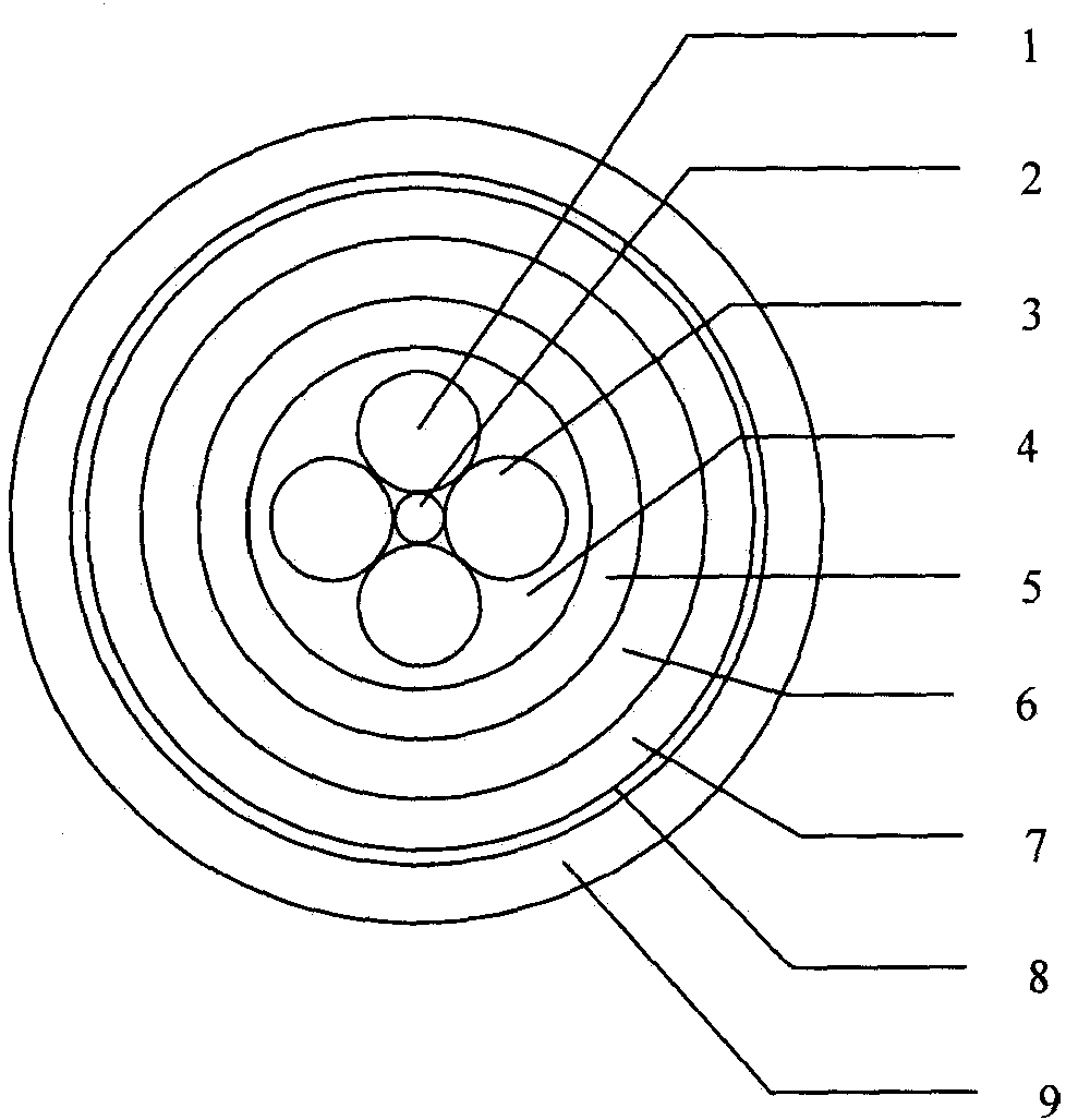
[0019] figure 2 It is a structural schematic diagram of the photoelectric composite cable for aerostats of the present invention. As shown in the figure, the photoelectric composite cable is composed of a cable core, a non-metallic reinforcement 6, a middle sheath 7, a lightning discharge layer 8 and a semiconductor outer sheath from the inside to the outside. Set of 9. The cable core includes a central piece 2, a power conductor 1, an optical fiber unit 3, a non-metallic internal reinforcement 4 and a polyethylene inner sheath 5; the power conductor 1 and the optical fiber unit 3 are twisted around the central piece 2 in layers, and the power conductors twisted in layers 1 and the fiber unit 3 are non-metallic reinforcements 4, and the outermost layer of the cable core is a polyethylene inner sheath 5. In this embodiment, the cent...


PUM


Abstract

The present invention proposes a photoelectric composite cable for aerostats with good mechanical properties and long service life. The positions in the cable are from the inside to the outside: the cable core, the non-metallic reinforcement, the middle sheath, the lightning protection layer and the outer sheath; the non-metallic reinforcement is made of insulating material; the middle sheath is made of insulating material; the lightning protection layer It is used to discharge lightning strike current, which adopts grid structure and is made of copper material; the middle sheath and the outer sheath are closely bonded together through the mesh of the lightning discharge layer. The cable core consists of a central piece, an optical fiber unit, a power conductor, a non-metallic inner reinforcement and an inner sheath from the inside to the outside; the fiber optic unit and the power conductor layer are twisted around the center piece. The invention can be applied to supply power and provide communication channels for aerostats such as tethered balloons and airships, and can also be applied to other occasions such as ship towing systems.

Description

technical field [0001] The invention belongs to the technical field of photoelectric transmission equipment, and in particular relates to a photoelectric composite cable for an aerostat. technical background [0002] The mooring cable of the aerostat requires high tensile strength (required working tension 13kN, breaking tension 40kN), strong pressure resistance (lateral pressure resistance 3kN / 100mm), and can provide a grounding path for a lightning current less than or equal to 50kA. It is also important to keep it as small as possible. The photoelectric composite cable used for aerostats is one of the mooring cables for aerostats. Firstly, it is required that the tensile force should reach a predetermined target, and that it can be retracted repeatedly, with good overall consistency; secondly, it must be able to protect the fragile optical fibers and power wires. This is a prerequisite to ensure the smooth communication system and power transmission system of the aerosta...

Claims


Application Information

Patent Timeline
Patent Type & Authority Patents(China)
IPC IPC(8): H01B11/22G02B6/44
Inventor 黄继东汪波陶景升袁松何钟鹍李鹏徐文娟郑兰荣杨春梅
Owner 8TH RES INST OF CETC
Learn More