Pyrolysis gas dust remover-filter

A filtration device and pyrolysis gas technology, applied in the direction of gas dust removal, membrane filter, dispersed particle filtration, etc., can solve the problems of affecting dust removal efficiency, complex design structure, easy to block the filter element quickly, etc., to achieve uniform and stable airflow distribution Quick connect effect

Active Publication Date: 2016-11-23
HENAN DRAGON INTO COAL TECH CO LTD
View PDF5 Cites 1 Cited by
  • Summary
  • Abstract
  • Description
  • Claims
  • Application Information

AI Technical Summary

Problems solved by technology

Currently commonly used are: cyclone centrifugal dust removal, electrostatic dust removal, solid particle dust removal, etc. The disadvantage of cyclone centrifugal dust removal is that it cannot filter dust with a diameter of less than 10 μm, and the dust removal efficiency is low; electrostatic dust removal requires the resistivity of the dust itself to be controlled at a certain level. range, so its design structure is complicated and the cost is high
[0003] The problem of solid particle dust removal is that the dust will continue to accumulate and bond between solid particles, which will affect the dust removal efficiency, and the increase in the pressure in the dust removal device will pose a safety hazard: application number 201210180811.5 discloses a particle dust removal filter and a dust removal filtration method
This invention uses solid particle materials as filter media to purify high-temperature dusty gas, or remove dust, heavy tar and other impurities in pyrolysis gas. The disadvantage is that the solid particle materials used need to be continuously added to ensure The dust removal effect makes the dust removal process complicated in this aspect, and when the tar and dust adhere to the solid particle material, it will cause bonding, which will cause the discharge port to be blocked.
The commonly used structural design of the device is: the first scheme: the inlet of the pyrolysis gas is set near the upper part of the air inlet chamber of the dust collector, that is, the partition near the filter body. For the vertically suspended filter element, the horizontal force of the airflow can easily break the filter element. At the same time, the airflow is extremely unevenly distributed in the dust collector, and the dust is evenly distributed in various parts of the filter body. The filter element is on the front and back of the airflow. The amount of dust is more different, which affects the filtering ability of the filter element; another solution: the inlet of the pyrolysis gas is set below the lower end of the filter element of the filter body, that is, the inlet of the pyrolysis gas is lower than the lower end of the filter element, which causes the pyrolysis gas When filtering, the airflow is always rising, and the filtered dust is blocked by the rising airflow in the process of falling, and the dust will be raised and filtered again. The dust is not easy to fall from the filter element area, and the filter element is easily blocked quickly.

Method used


Image

  • Pyrolysis gas dust remover-filter
  • Pyrolysis gas dust remover-filter
  • Pyrolysis gas dust remover-filter

Examples


Embodiment 1

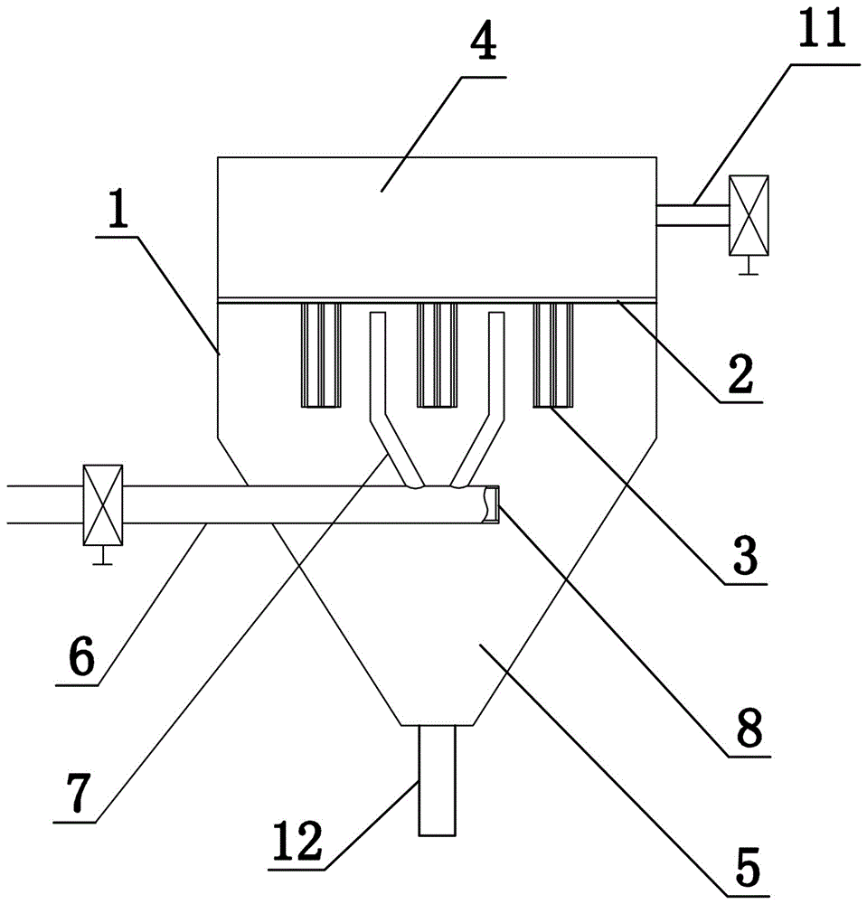
[0026] Such as figure 1 and figure 2 As shown, the present invention includes a dust collector 1 and a diversion mechanism. The dust collector 1 is an upper cylinder and a lower conical structure. A filter mechanism is arranged in the dust collector 1. The filter mechanism includes a partition 2 and a plurality of vertically fixed partitions on the partition 2. Filter element 3, the filter element 3 of present embodiment is with three, through dividing plate 2, dust remover 1 is divided into the air outlet chamber 4 that is positioned at the top and the air inlet chamber 5 that is positioned at the bottom, and described air outlet chamber 4 upper end is provided with air outlet pipe 11, enters A dust collection pipe 12 is provided at the lower end of the air chamber 5;

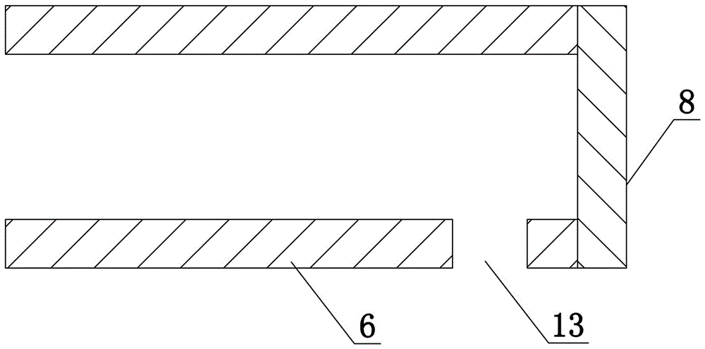
[0027] The flow guiding mechanism includes a main pipe 6 and a branch pipe 7 that communicate with each other. The main pipe 6 runs through the wall of the dust collector 1 horizontally and extends into the ...

Embodiment 2

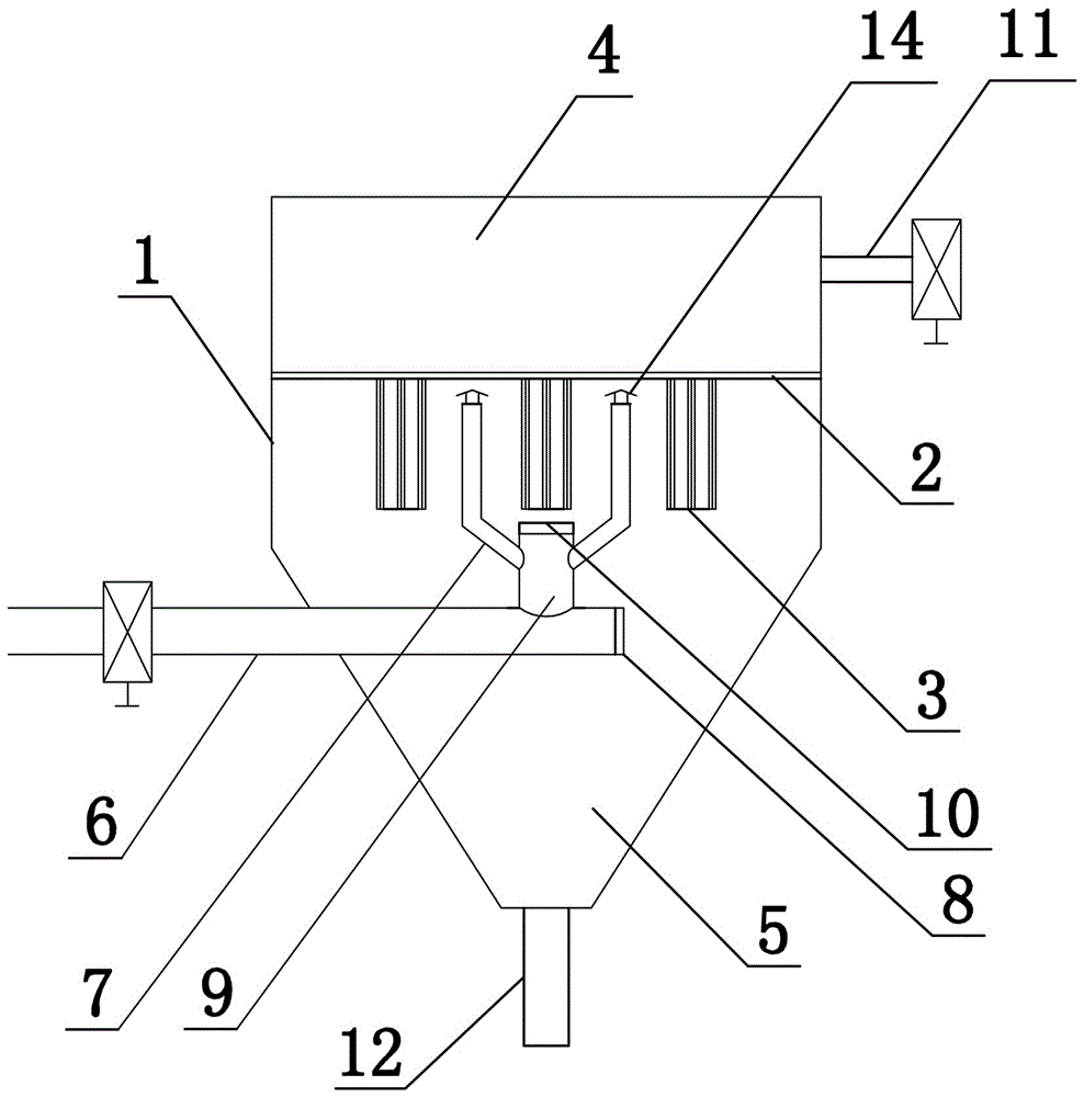
[0029] Such as image 3 and Figure 4 As shown, the present invention includes a dust remover 1 and a diversion mechanism. The dust remover 1 is an upper cylinder and a lower conical structure. The filter mechanism is fixedly connected in the dust remover 1. The filter mechanism includes a partition 2 and a vertically fixed connection on the partition 2. A plurality of filter cores 3, three filter cores 3 in this embodiment, the dust collector 1 is divided into an upper air outlet chamber 4 and a lower air inlet chamber 5 through the partition plate 2, and an air outlet pipe 11 is provided at the upper end of the air outlet chamber 7 , the lower end of the air intake chamber 5 is provided with a dust collection pipe 12;

[0030] The guide mechanism includes a main pipe 6, a branch pipe 7 and a vertical pipe 9. The main pipe 6 runs through the wall of the dust collector 1 horizontally and extends into the air inlet chamber 5 and is located near the central axis of the dust col...

Embodiment 3

[0032] Such as Figure 5 As shown, the present invention includes a dust collector 1 and a diversion mechanism. The dust collector 1 is an upper cylinder and a lower conical structure. A filter mechanism is arranged in the dust collector 1. The filter mechanism includes a partition 2 and a plurality of vertically fixed partitions on the partition 2. Filter element 3, there are three filter elements 3 in this embodiment, and a plurality of grooves or arc-shaped diversion grooves are arranged on the partition plate 2 between adjacent filter elements. The plate 2 divides the dust collector 1 into an air outlet chamber 4 located above and an air inlet chamber 5 located below, the upper end of the air outlet chamber 7 is provided with an air outlet pipe 11, and the lower end of the air inlet chamber 5 is provided with a dust collection pipe 12;

[0033]The flow guiding mechanism includes a main pipe 6 and a branch pipe 7 that communicate with each other. The main pipe 6 runs throug...


PUM

PropertyMeasurementUnit
diameteraaaaaaaaaa

Abstract

The invention discloses a pyrolysis gas dust remover-filter, comprising a dust remover and a guide mechanism; a filter mechanism is disposed in the dust remover; the filter mechanism divides the dust remover into an upper exhaust chamber and a lower intake chamber; the guide mechanism comprises a main pipe and a branch pipe; the main pipe runs through the dust remover and extends into the intake chamber; the end of the main pipe extended into the intake chamber is a seal end, the branch pipe is arranged on the main pipe extended into the intake chamber, the upper end of the branch pipe is positioned below the filter mechanism, the lower end of the branch pipe is communicated with the main pipe, the upper end of the branch pipe is an open end, and the exhaust chamber is provided with an exhaust pipe. The main pipe and the branch pipe cooperate to enable the flow direction of high-temperature pyrolysis gas to be consistent with the return direction of dust, and thus the problems of reentrainment of dust and breakage of filter elements are prevented effectively.

Description

technical field [0001] The invention belongs to the technical field of filter and dust removal, and in particular relates to a pyrolysis gas dust removal filter device produced by coal pyrolysis and biomass pyrolysis. Background technique [0002] The temperature of the pyrolysis gas produced by coal pyrolysis and biomass pyrolysis is 300~700°C, and the pyrolysis gas carries a small amount of raw material dust. Before collecting the pyrolysis gas, it needs to be dedusted by a high-temperature dust collector. The final pyrolysis gas can be effectively used in the subsequent process. Currently commonly used are: cyclone centrifugal dust removal, electrostatic dust removal, solid particle dust removal, etc. The disadvantage of cyclone centrifugal dust removal is that it cannot filter dust with a diameter of less than 10 μm, and the dust removal efficiency is low; electrostatic dust removal requires the resistivity of the dust itself to be controlled at a certain level. Within ...

Claims


Application Information

Patent Timeline
Patent Type & Authority Applications(China)
IPC IPC(8): C10K1/02B01D46/00
CPCB01D46/0041C10K1/024B01D2267/70B01D46/58
Inventor 朱书成王希彬
Owner HENAN DRAGON INTO COAL TECH CO LTD
Why Eureka
Try Eureka