
Domestic waste incinerator

A technology for domestic waste incineration and grate, which is applied to incinerators, combustion types, combustion methods, etc., can solve the problems of kiln system shutdown and maintenance, no cooling slag, and water-cooled slag machine consuming large cooling water. To avoid the waste of equipment investment and water resources, improve safety and reliability, and improve energy efficiency

Active Publication Date: 2018-07-24
NANJING KISEN INT ENG
View PDF6 Cites 0 Cited by
  • Summary
  • Abstract
  • Description
  • Claims
  • Application Information

AI Technical Summary

Problems solved by technology

[0003] First, the grate furnace device in the waste incineration power plant itself does not have the function of cooling the slag, but cools the slag by installing a water-cooled slag extractor under the waste slag outlet
The use of water-cooled slag discharger has the following disadvantages when co-processing domestic waste in cement kilns: 1) The water-cooled slag contains moisture, and when the slag enters the cement kiln system for use (such as grinding the slag as a raw material into cement raw meal, and then sending it into cement The firing system of the production line is fired into cement clinker), which needs to be dried first, which consumes more heat; 2) the water-cooled slag discharger needs to consume a large amount of cooling water, and needs a separate circulating water treatment system with strict sealing requirements , high maintenance costs; 3) The water vapor generated when cooling the slag enters the waste incinerator, affecting the stability of the waste incineration system and reducing the service life of the refractory material of the waste incineration device; 4) The wear and deformation of the water-cooled slag machine is large, Problems such as failure and shutdown affect the stable operation of the incinerator system
[0004] Second, after reducing the water-cooled slag extractor to the existing incinerator, the slag generated after incinerating domestic waste cannot be effectively cooled, and the residual heat energy in the hot slag cannot be effectively utilized
The reasons are as follows: 1) The primary air currently used is hot air, the temperature of which is mostly above 200°C, and has a limited cooling effect on high-temperature slag; 2) The hearth of the existing grate furnace is a separate chamber with only one air outlet. Low-temperature cooling air cannot be introduced; 3) Due to the control requirements for pollutants such as dioxins, the control of the incineration temperature is very strict, and the total air volume entering the combustion area of ​​the incineration device is limited by temperature; 4) The existing grate The furnace uses a water-cooled slag extractor to cool the hot slag, and the high-grade heat energy of the hot slag is absorbed by the circulating cooling water
[0005] Third, the downtime of grate furnaces in traditional waste incineration power plants is relatively long, requiring 2 to 3 days, which has an impact on the shutdown and maintenance of the kiln system; especially the shutdown of waste incinerators due to emergencies A large amount of unburned waste and flue gas will inevitably affect the stable operation of the cement kiln system. It is necessary to shorten the shutdown time of the grate furnace as much as possible and quickly cool the unburned waste.

Method used


Image

  • Domestic waste incinerator
  • Domestic waste incinerator

Examples


Embodiment Construction

[0025] In order to make the object, technical solution and advantages of the present invention clearer, the present invention will be further described in detail below in conjunction with specific implementation methods and accompanying drawings. Here, the exemplary embodiments and descriptions of the present invention are used to explain the present invention, but not to limit the present invention.

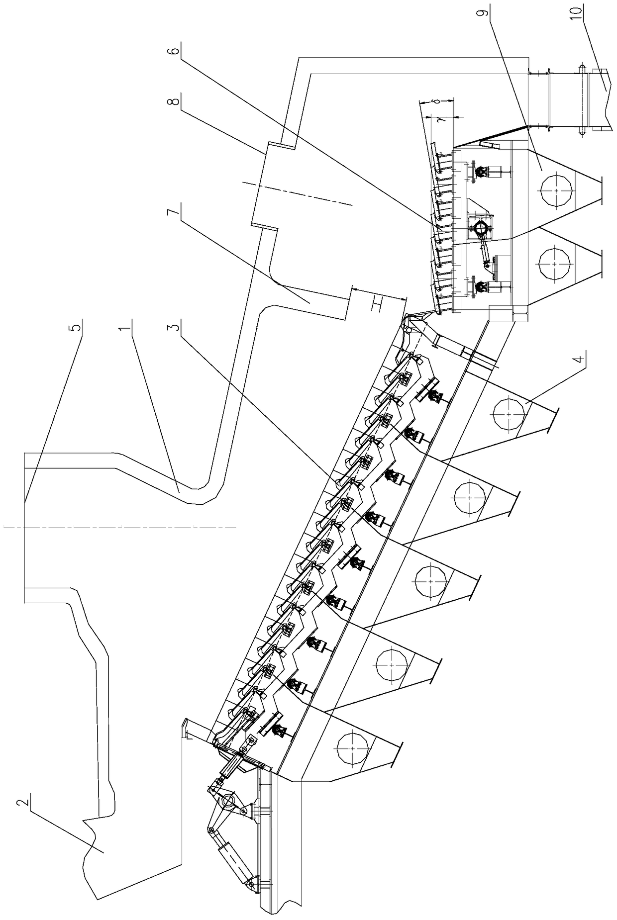
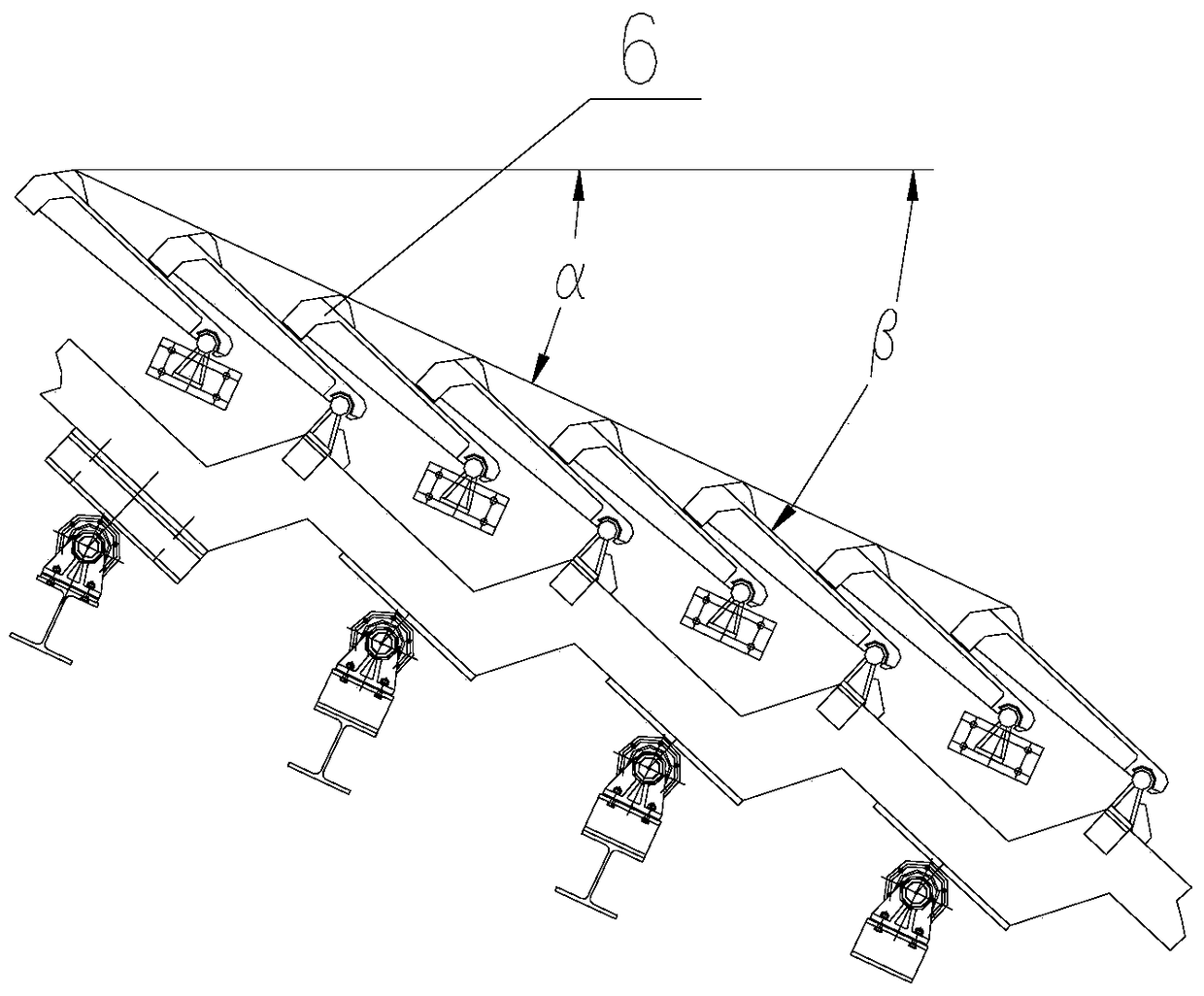
[0026] Such as figure 1 , figure 2 As shown, the domestic waste incinerator of the present invention includes a furnace body 1, a feed port 2, an incineration grate 3, a primary air chamber 4, a high-temperature flue gas outlet 5, a cooling grate 6, a windshield device 7, and a hot air outlet 8. Cooling air chamber 9 and discharge port 10; a feed port 2 is provided on the top wall on the left side of the furnace body 1; a high-temperature flue gas outlet 5 is provided on the upper part of the furnace body 1, and an incinerator is provided below the high-temperature flue gas ou...


PUM


Abstract

The invention relates to an incineration equipment, in particular to a domestic waste incinerator mainly used for incinerating low-calorific value, high-moisture and undecomposed domestic waste, which is matched with a cement kiln for co-processing domestic waste; including a furnace body and a feed port , incineration grate, primary air chamber, high-temperature flue gas outlet, cooling grate, windshield device, hot air outlet, cooling air chamber and discharge port; in the technical scheme of the present invention, by adding a primary After the incineration grate, a cooling grate, a hot air outlet and a cooling air chamber are installed, omitting the slag cooling link of the water-cooled slag extractor, avoiding redundant equipment investment and waste of water resources; The hot air is recovered and returned to the drying section or incineration section of the incinerator, and the heat energy emitted when the slag is cooled is effectively used; the downtime is greatly shortened, the energy utilization rate is improved, the energy consumption is reduced, and the The safety and reliability of machine operation.

Description

technical field [0001] The invention relates to an incineration device, in particular to a domestic waste incinerator mainly used for incinerating low-calorific value, high-moisture and undecomposed domestic waste, which is matched with a cement kiln for co-processing domestic waste. Background technique [0002] Municipal solid waste disposal has become a worldwide concern, and it is also a very difficult task. At present, the more effective treatment method is the incineration method, which is also the garbage treatment method commonly used in countries all over the world; from the perspective of thoroughness, harmlessness and environmental protection of garbage disposal, the garbage incineration device and the cement burning system are combined. Disposal of domestic waste is an ideal way of waste disposal. Among them, the floor-burning garbage incineration device has the characteristics of not needing to sort garbage and is suitable for high-moisture, low-calorific-value...

Claims


Application Information

Patent Timeline
Patent Type & Authority Patents(China)
IPC IPC(8): F23G5/04F23G5/44F23G5/46
Inventor 徐连春徐靖李安平陈新平陈艳征
Owner NANJING KISEN INT ENG
Learn More