

Engineering comprehensive hole measuring system and method based on in-hole camera shooting and single-hole sound waves
A single-hole acoustic wave engineering technology, which is applied in the field of engineering comprehensive hole measurement system, can solve the problems affecting the accuracy of depth measurement, water turbidity, and the influence of sound wave detection, so as to improve the clarity and the coupling degree of drilling sound waves, and improve the clarity of imaging degree, the effect of reducing the detection time
- Summary
- Abstract
- Description
- Claims
- Application Information
AI Technical Summary
Problems solved by technology
Method used
Image

Examples
Embodiment Construction
[0068] The present invention will be further described below in conjunction with the accompanying drawings and embodiments.
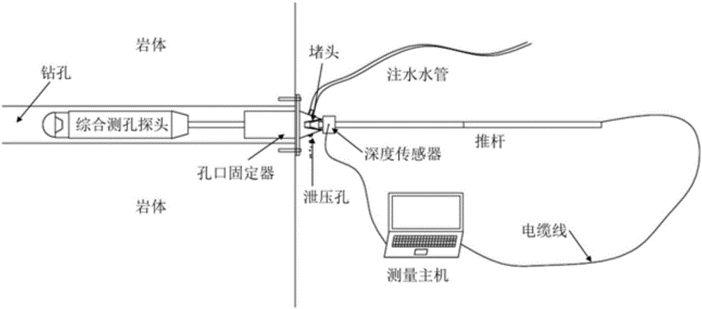
[0069] Such as figure 2 As shown in Fig. 1, an engineering comprehensive hole measuring system based on in-hole camera and single hole sound wave mainly includes a measuring host, a comprehensive probe, a probe push rod, a hole fixing device and a depth sensor. Before the measurement, the integrated probe is put into the drilled hole in advance, the probe push rod is fixed on the probe, the hole holder 22 and the depth sensor are sleeved on the push rod, the hole holder 22 moves forward, and is fixed to the In the drilling, the cable is connected to the measuring host, and the drilling data is collected by pushing the push rod hole 39 at a constant speed during measurement;
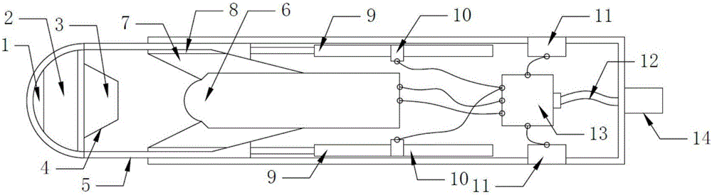
[0070] Such as image 3As shown, the comprehensive probe mainly includes a temperature tester 1, a compass and a temperature display panel 3, a high-strength light-transmitting ...
PUM
 Abstract
Description
Claims
Application Information