Optical fiber repeater branching transmission method and branching optical fiber repeater

A technology of optical fiber repeater and transmission method, which is applied in the field of wireless communication relay transmission, can solve the problems of insufficient transmission distance, high cost, and inconsistent user distribution, so as to reduce the number of antennas used, improve the isolation of sending and receiving, and reduce the mutual interference effect

Active Publication Date: 2016-11-23
SHENZHEN GREAT LOONG BROTHER IND CO LTD
View PDF3 Cites 4 Cited by
  • Summary
  • Abstract
  • Description
  • Claims
  • Application Information

AI Technical Summary

Problems solved by technology

[0002] In the current wireless system, there are many kinds of wireless communication systems, such as GSM, CDAM, WCDMA, TD-SCDAM, CDMA2000 and other wireless communication systems. In the existing technology, there are dedicated optical fibers for the above wireless communication systems. The repeater is used as a relay device, but due to some special areas and tunnels, due to the limitations of the antenna installation space and the number of optical fibers brought about by its location and building boundaries, the network planning of each wireless communication system is inconsistent, and the network planning of each system is inconsistent. Influenced by factors such as base station location, optical transmission route length, inconsistent user distribution, mutual interference, and isolation requirements between systems, all relay equipment cannot be installed in these areas to meet the requirements of each wireless communication system. Therefore, the existing optical fiber repeater cannot meet the relay communication requirements of each wireless communication system user in this type of area; the comparative technology similar to the present invention is: Patent No. 2009102162372, optical fiber repeater transmission processing method and Variable channel transmission optical fiber repeater, which introduces some solutions to the above problems, but in the comparison technology, wavelength division multiplexing technology is used. From the current technical development situation, the channel utilization rate of wavelength division multiplexing technology is not high. High, high cost, and the transmission distance is not far enough to meet the needs of practical applications

Method used


Image

  • Optical fiber repeater branching transmission method and branching optical fiber repeater
  • Optical fiber repeater branching transmission method and branching optical fiber repeater
  • Optical fiber repeater branching transmission method and branching optical fiber repeater

Examples


Embodiment Construction

[0016] Embodiment of the present invention is described below with accompanying drawing as example;

[0017] Figure 1 to Figure 3 The same number in the corresponding device and module name and function are the same;

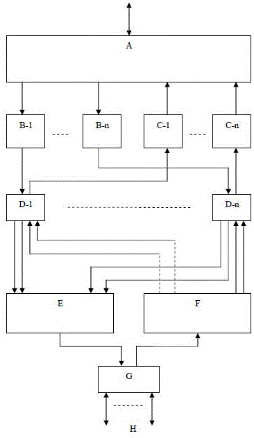
[0018] figure 1 It is the overall electrical principle diagram of the split-type optical fiber repeater station in an embodiment of the present invention, wherein: A is a wireless signal splitter, B-1~B-n are wireless receivers, and C-1~C-n are Wireless transmitter, D-1~D-n are optical transmission signal adapters, E is time division multiplexer with photoelectric conversion, F is time division multiplexer with photoelectric conversion, G is optical transmission interface, H is External optical fiber;

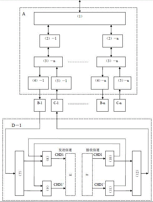
[0019] figure 2 It is a detailed electrical schematic diagram of the split-type optical fiber repeater station in an embodiment of the present invention, in which the circuit parts with the same function are omitted, such as the optical transmission signal ...


PUM


Abstract

The invention discloses a branching optical fiber repeater which is composed of a power source, a microprocessor, an antenna feed system, a wireless receiver, a wireless transmitter, optical fiber, an analog-digital converter, a digital-analog converter, a time division multiplexing device, a time division de-multiplexing device, a wireless signal dividing and combining unit, an optical transmission signal adaptor, an optical transmission interface and other modules. An optical fiber repeater branching transmission method is capable of providing wireless communication relay transmission service for various types of wireless communication system users in a special region and tunnels, reducing the number of antennae and optical fiber, increasing relay transmission distance, reducing system cost and reducing mutual interference between systems and suitable for carrying out relay transmission for various wireless communication systems.

Description

technical field [0001] The invention is a wireless communication relay transmission technology, which is suitable for relay transmission of a wireless communication system in a weak field section, and belongs to the technical field of wireless communication. Background technique [0002] In the current wireless system, there are many kinds of wireless communication systems, such as GSM, CDAM, WCDMA, TD-SCDAM, CDMA2000 and other wireless communication systems. In the existing technology, there are dedicated optical fibers for the above wireless communication systems. The repeater is used as a relay device, but due to some special areas and tunnels, due to the limitations of the antenna installation space and the number of optical fibers brought about by its location and building boundaries, the network planning of each wireless communication system is inconsistent, and the network planning of each system is inconsistent. Influenced by factors such as base station location, op...

Claims


Application Information

Patent Timeline
Patent Type & Authority Applications(China)
IPC IPC(8): H04B10/2575H04B10/29H04B10/80H04J3/08
CPCH04B10/25752H04B10/29H04B10/802H04J3/08
Inventor 耿直
Owner SHENZHEN GREAT LOONG BROTHER IND CO LTD
Why Eureka
Try Eureka