Oblique lathe bed double-spindle and double-row-tool numerical control lathe capable of achieving automatic feeding and discharging inside

A technology of automatic loading and unloading, CNC lathes, applied in automatic lathes/semi-automatic lathes, turning equipment, turning equipment and other directions, can solve the problems of affecting the accuracy of machining workpieces, troublesome adjustment of hydraulic lathes, and high degree of environmental pollution, to improve machining accuracy, The protective appearance is novel and the protective design is simple.

Active Publication Date: 2016-12-07
SHENYANG MASCH TOOL CO LTD
View PDF9 Cites 3 Cited by
  • Summary
  • Abstract
  • Description
  • Claims
  • Application Information

AI Technical Summary

Problems solved by technology

[0002] At present, when processing small bearing rings in China, most of them use semi-automatic hydraulic lathes, and a bearing ring workpiece is processed sequentially by several hydraulic lathes. The hydraulic lathes are troublesome t

Method used


Image

  • Oblique lathe bed double-spindle and double-row-tool numerical control lathe capable of achieving automatic feeding and discharging inside
  • Oblique lathe bed double-spindle and double-row-tool numerical control lathe capable of achieving automatic feeding and discharging inside
  • Oblique lathe bed double-spindle and double-row-tool numerical control lathe capable of achieving automatic feeding and discharging inside

Examples


Embodiment Construction

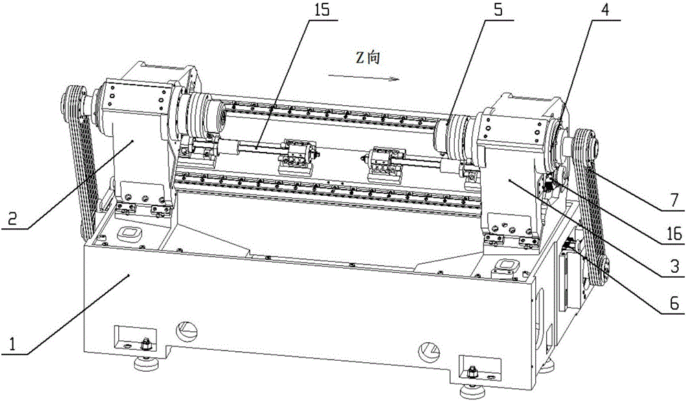
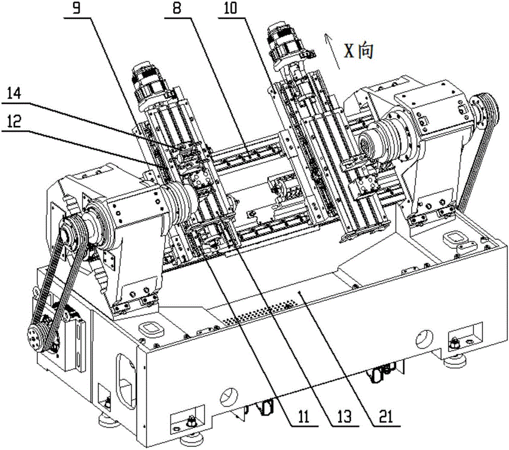
[0024] Such as figure 1 As shown, the bed 1 is provided with opposite spindle boxes 2 and 3, the spindle unit 4 is installed in the spindle box, the clamping device 5 is installed at the front end of the spindle unit, the spindle and the spindle power main motor 6 are connected by a belt 7, and the double spindle The boxes are respectively fixed with bolts and positioning pins, such as figure 2 As shown, the bed 1 adopts an integral casting inclined bed, and the inner cavity of the two Z-axis guide rails 8 is arranged with 5 horizontal ribs. The upper surface of the bed is funnel-shaped. The Z-axis guide rail supports the middle. This layout is compact and has strong torsion resistance and shock resistance.

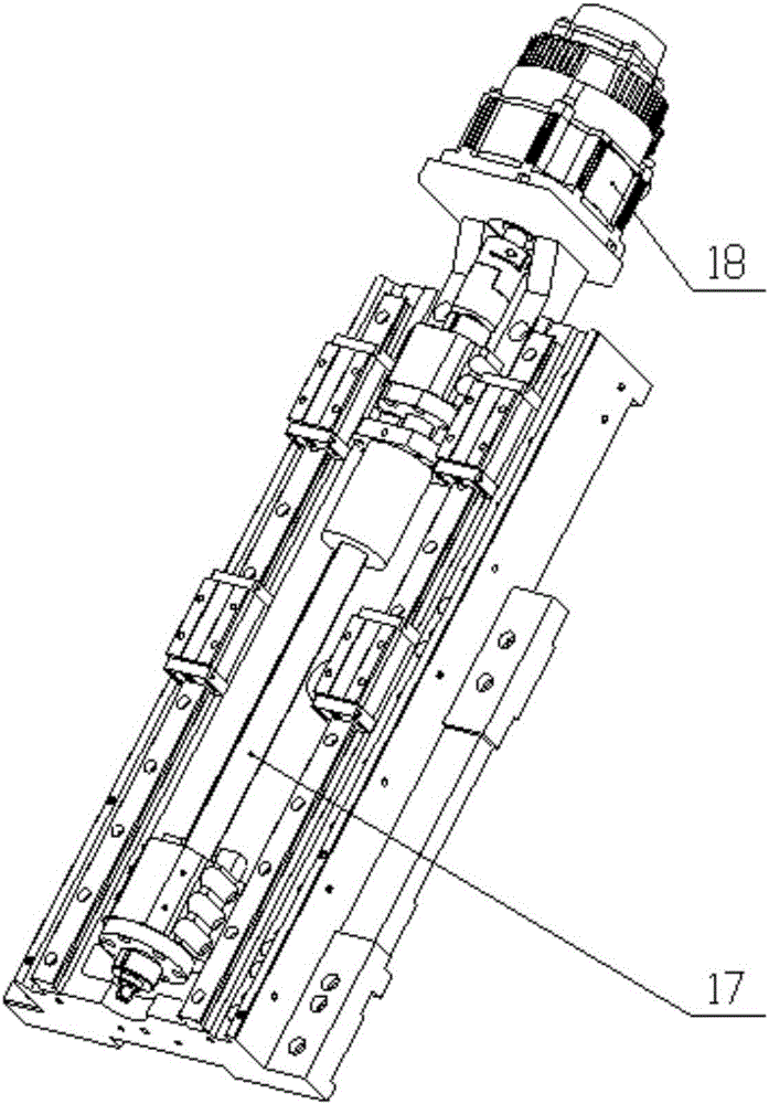
[0025] Such as figure 2 , image 3 As shown, two double saddles perpendicular to the spindle direction are placed on the bed.

[0026] Two Z-axis linear guides are placed on the bed, and the Z-axis linear guides contain 8 sliders. The left saddle 9 cooperates with t...


PUM


Abstract

The invention discloses an oblique lathe bed double-spindle and double-row-tool numerical control lathe capable of achieving automatic feeding and discharging inside. A lathe bed is provided with a left spindle box and a right spindle box which are oppositely arranged. Spindle units are arranged in the spindle boxes. Material clamping devices are arranged at the front ends of the spindle units. The spindles are connected with spindle power main servo motors through belts. A left saddle and a right saddle are arranged on the lathe bed in the Z direction in parallel and can move left and right in the Z direction. Sliding plates are arranged on the left saddle and the right saddle and move in the X direction in the corresponding saddles. The left spindle box and the right spindle box are symmetrically arranged with the center of the lathe bed as the symmetric face, the saddles are symmetrically arranged with the center of the lathe bed as the symmetric face, the sliding plates are symmetrically arranged with the center of the lathe bed as the symmetric face, and row tool plates are symmetrically arranged with the center of the lathe bed as the symmetric face. An automatic lathe interior feeding and discharging mechanism is arranged on the lathe bed and the spindle boxes, a scrap discharging box is arranged at the bottom of the lathe bed, outer protection parts are arranged on the lathe bed, and spindle control system double CRT boxes are fixed to the outer protection part. Accurate machining in all procedures including bearing ring inner circles, outer circles, end faces, chamfers, grooves, dustproof grooves and the like is finished on one machine tool, original machining procedures of several machine tools are combined to be conducted on one machine tool, the occupied area is reduced, and the production efficiency is improved.

Description

technical field [0001] The invention relates to machine tool manufacturing in mechanical processing, and is a special numerical control machine tool specially developed for processing bearing rings. Background technique [0002] At present, when processing small bearing rings in China, most of them use semi-automatic hydraulic lathes, and one bearing ring workpiece is processed sequentially by several hydraulic lathes. The hydraulic lathes are troublesome to adjust, the process is scattered, the floor space is large, the equipment has no protection, and the degree of environmental pollution is high. , The degree of automation is low, which affects the precision requirements of the processed workpiece. Contents of the invention [0003] The purpose of the present invention is to provide a double-spindle, double-row knife, automatic loading and unloading lathe in the machine, so as to realize the inner circle, outer circle, end face, chamfer, groove, dust-proof groove, etc. ...

Claims


Application Information

Patent Timeline
IPC IPC(8): B23B9/08B23Q7/08B23Q7/10B23Q11/08
CPCB23B9/08B23Q7/08B23Q7/10B23Q11/0891
Inventor 任延伟刘大敏柏杉王伟平周兆祥曾德强张怀宇王雪于春明赵星王亮刘洪强张伟刘萍戚远大吕文卓李安刘星张运芝邱岩曹维佳黄一师王庆博于海波于铎李欣尚陆华段雪峰周阳李宁张金军陈岩王国玉陈涛苏可
Owner SHENYANG MASCH TOOL CO LTD
Why Eureka
Try Eureka