Micro-channel cooling system of air inlet duct of supersonic vehicle

A cooling system and micro-channel technology, applied in the direction of supersonic aircraft, cooling system of power plant, aircraft, etc., can solve problems such as inability to protect the cooling of the air intake, reduce the reliability of parts, and ablation of the wall of the air intake , to achieve the effects of improving cycle thermal efficiency, improving atomization, and small diffusion resistance

Inactive Publication Date: 2016-12-07
XIAMEN UNIV
View PDF6 Cites 3 Cited by
  • Summary
  • Abstract
  • Description
  • Claims
  • Application Information

AI Technical Summary

Problems solved by technology

However, for the heat continuously generated by high Mach number and long-term flight, simply relying on the heat capacity of its own structural materials to absorb it will cause the overall engine to heat up rapidly, reduce the reliability of parts, and even cause ablation of the wall surface of the air inlet.
As for the cooling method of the coating, there is a limit value that can withstand the total heat, which cannot provide high-efficiency and long-term cooling protection for the air inlet (Shi Liping, He Xiaodong. Thermal protection system for reusable spacecraft Overview[J].Aviation Manufacturing Technology,2004(07):80-82.)

Method used


Image

  • Micro-channel cooling system of air inlet duct of supersonic vehicle
  • Micro-channel cooling system of air inlet duct of supersonic vehicle
  • Micro-channel cooling system of air inlet duct of supersonic vehicle

Examples


Embodiment Construction

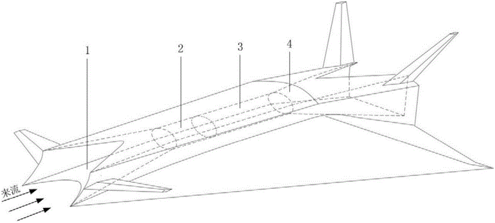
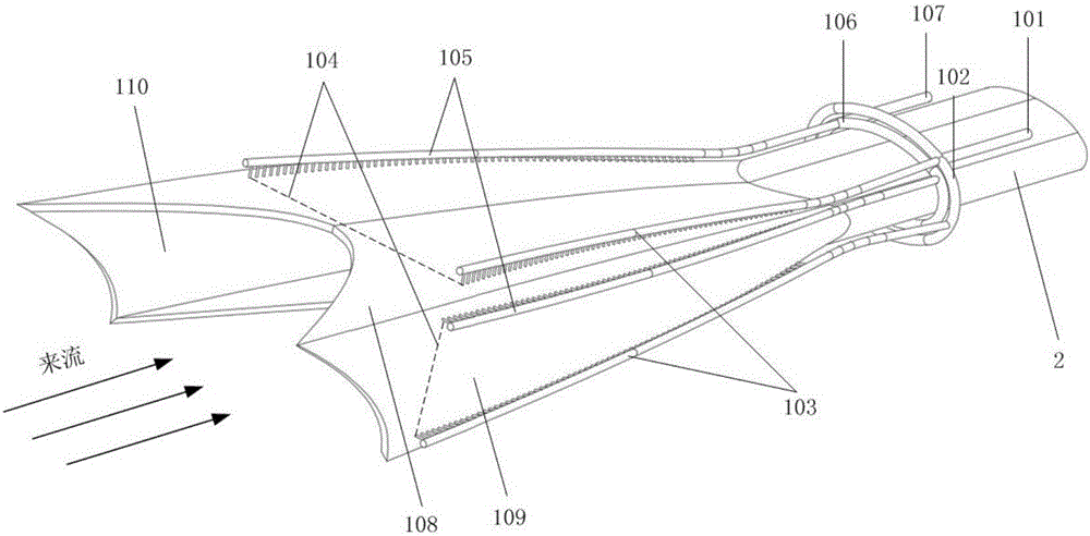
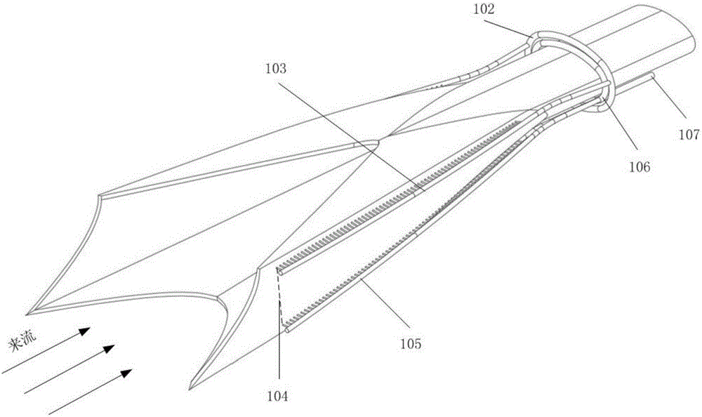
[0021] Such as Figure 1~5 As shown, the embodiment of the present invention is provided with a main flow inlet 101, an annular inlet main flow channel 102, an inlet main flow channel 103, a microchannel 104, an outlet main flow channel 105, an annular outlet main flow channel 106 and a main flow outlet 107;

[0022] The mainstream inlet 101 is located above the engine isolation section, and the cold aviation kerosene enters the annular inlet main channel 102 from the mainstream inlet 101 as a coolant, and the annular inlet main channel 102 is located outside the engine isolation section, and the coolant is divided into three strands in the annular inlet main channel, Enter the inlet main channel 103 above the lower wall, the left wall, and the right wall of the air inlet respectively, and the cooling liquid enters the microchannel 104 on the respective wall from the inlet main channel 103 above the different walls, and the microchannel 104 is located on the wall of the air inl...


PUM


Abstract

The invention provides a micro-channel cooling system of an air inlet duct of a supersonic vehicle. The micro-channel cooling system is provided with a main flow inlet, an annular inlet main flow duct, an inlet main flow duct, micro channels, an outlet main flow duct, an annular outlet main flow duct and a main flow outlet. The main flow inlet is located above a separation section of an engine. Cooling liquid enters the annular inlet main flow duct from the main flow inlet. The annular inlet main flow duct is located on the outer side of the separation section of the engine. The cooling liquid is divided into three ways in the annular inlet main flow duct, and the three ways of the cooling liquid enter the portions, located above the lower wall face of the air inlet duct, the left wall face of the air inlet duct and the right wall face of the air inlet duct, of the inlet main flow duct correspondingly. The cooling liquid enters the micro channels on the corresponding wall faces from the portions, located above the different wall faces, of the inlet main flow duct. The micro channels are located in the wall faces of the air inlet duct, are used for cooling the wall faces and air, and then enter a combustion chamber. The cooling liquid absorbs heat in the micro channels, enters the portions, above the different wall faces, of the outlet main flow duct, flows into the annular outlet main flow duct located above the separation section, and flows out through the main flow outlet. The cooling liquid flows out of the main flow outlet and enters the combustion chamber to be mixed with air for combustion, and then the cooling liquid is sprayed out of an exhaust nozzle.

Description

technical field [0001] The invention relates to a supersonic aircraft, in particular to a supersonic air intake micro-channel cooling system suitable for high Mach number and long-time voyage. Background technique [0002] Hypersonic vehicle technology is the new commanding height of aerospace technology in the 21st century. It is the third epoch-making milestone in the history of aviation after the invention of aircraft and breaking through the sound barrier. However, there are still many technical problems. When the aircraft is flying at a high Mach number and in the air for a long time, the incoming flow velocity of the gas in the inlet can reach Mach 5 or more, and the stagnation temperature of the incoming flow will reach above 1500K. The flow velocity at the wall is zero, that is, the temperature of the airflow close to the wall of the inlet can reach the stagnation temperature at this time. For long-endurance flight, the heat load on the wall surface of the air inlet...

Claims


Application Information

Patent Timeline
Patent Type & Authority Applications(China)
IPC IPC(8): B64C30/00B64D33/08
CPCB64C30/00B64D33/08
Inventor 邢菲蔡江千李俊黄玥林志伟罗灿
Owner XIAMEN UNIV
Why Eureka
Try Eureka