Mud film composite sbr water treatment process

A water treatment and process technology, applied in the field of mud film composite SBR water treatment process, can solve the problems of packing leakage, discharge with water, poor effect, etc., and achieve the effect of high volume load, continuous water in and out, and simple operation and management

Active Publication Date: 2019-02-15
QINGDAO SPRING WATER TREATMENT
View PDF5 Cites 0 Cited by
  • Summary
  • Abstract
  • Description
  • Claims
  • Application Information

AI Technical Summary

Problems solved by technology

However, simply adding suspended fillers to the SBR system may cause filler leakage and discharge with water, etc.
In addition, although the traditional SBR process has an anoxic stirring time in theory, it can denitrify and denitrify, but the function is restricted by the drainage ratio and the utilization of influent carbon sources, so the effect is poor and needs to be further strengthened.

Method used


Image

  • Mud film composite sbr water treatment process

Examples


Embodiment 1

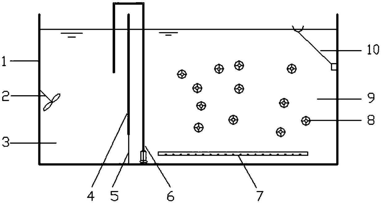
[0031] Take the effluent from the primary sedimentation tank of a city sewage treatment plant in winter as the influent water, the water temperature is 12-15°C, the concentration of BOD in the water is 165-180mg / L, the concentration of ammonia nitrogen is 30-40mg / L, the concentration of TN is 35-50mg / L, and the concentration of TP is 2- 3mg / L. Reactor effective volume 3.0m 3 , of which 1.2m in zone A 3 , 1.8m in zone B 3 . The specific surface area of ​​the suspended filler used is 620m 2 / m 3 , the filling rate is 20%, and the specific gravity before filming is 0.98. The design operation cycle is: water inflow 2h, reaction 1h, precipitation 0.5h, decanting water 0.5h. Single water change 0.8m 3 .

[0032] When starting up, the return sludge of the water plant is used as inoculation sludge, and new suspended filler is added. In the start-up phase, the single water change volume is 0.4m 3 . After 3 days of start-up, the filler is wetted and begins to hang the film, a...

Embodiment 2

[0034] Take the effluent from the primary sedimentation tank of a sewage treatment plant in winter as the influent, the water temperature is 12-15°C, the concentration of BOD in the water is 125-150mg / L, the concentration of ammonia nitrogen is 32-44mg / L, the concentration of TN is 37-50mg / L, and the concentration of TP is 2-3mg / L. Reactor volume 5.4m 3 , of which 2.4m in zone A 3 , 3.0m in Zone B 3 . A total of 2 monomer reactors are operated alternately. The specific surface area of ​​the suspended filler used is 620m 2 / m 3 , the filling rate is 25%, and the specific gravity before filming is 0.98. Due to the lack of carbon source in the water, a carbon source dosing device is installed in Area A to supplement the carbon source during the water inflow and reaction stage. The design operation cycle is: water inflow 2h, reaction 1h, precipitation 0.5h, decanting water 0.5h. 2 reactors alternately feed water to realize continuous water inlet and outlet operation, with...


PUM

PropertyMeasurementUnit
porosityaaaaaaaaaa

Abstract

The invention discloses a mud film composite SBR water treatment process. Firstly, in the water inlet stage, the water enters from the A area of ​​the SBR tank body, and the stirring device is turned on at the same time as the water inlet. With the increase of the water inflow, the water in the A area The mixture of water and raw sludge enters zone B through the water hole. At this time, the aeration device is turned on, and the reflux device is turned on at the same time; then it enters the reaction stage, the water intake is stopped, the stirring device and the aeration device continue to be turned on, and the reflux device continues to Operation, under the action of the reflux device, the mixed liquid in the B area is refluxed to the A area, and the A and B areas form a cycle; the sedimentation, the stirring device, the aeration device and the reflux device are closed, and the suspended filler and sludge are separated from the treated sewage; Drainage, the treated clean water is discharged through the decanter, and one operation cycle ends. By partitioning the SBR tank, the sludge mixture can circulate in the two zones under the action of the reflux device. Using this process to treat sewage has the advantages of high volume load and good water discharge effect.

Description

technical field [0001] The invention relates to the technical field of sewage treatment, in particular to a mud film composite SBR water treatment process. Background technique [0002] In order to strengthen the protection of the water environment, the country has put forward higher requirements on the quality of the effluent from sewage treatment plants. In addition, the amount of water treated by many sewage treatment plants is also increasing year by year. However, while the sewage treatment plant is increasing its standard and capacity, there is not enough land to build new structures, and it intends to meet the increased water volume and improve the quality of effluent water for pool capacity. Some new water plants also face the same problem because they occupy less land. [0003] Based on this situation, how to avoid increasing the pool volume, but to increase the volume load in the pool volume is the main development direction of the new sewage treatment process. I...

Claims


Application Information

Patent Timeline
Patent Type & Authority Patents(China)
IPC IPC(8): C02F3/30
CPCC02F3/302
Inventor 于振滨郑志佳宋美芹刘飞杨晓美杨宇星
Owner QINGDAO SPRING WATER TREATMENT
Why Eureka
Try Eureka