
Coal-fired power generation system simultaneously integrating slot type solar heat collecting system and tower type solar heat collecting system

A technology of tower solar energy and trough solar energy, applied in the field of integrated power generation of solar energy and coal-fired thermal power units, can solve problems such as increased reheat steam flow, reduced steam extraction, and hidden dangers of stable and safe operation of boiler units

Active Publication Date: 2016-12-07
NORTH CHINA ELECTRIC POWER UNIV (BAODING)
View PDF4 Cites 7 Cited by
  • Summary
  • Abstract
  • Description
  • Claims
  • Application Information

AI Technical Summary

Problems solved by technology

However, the effective integration of traditional conventional coal-fired power plants and trough solar heat collection systems is mostly concentrated on the heat recovery system of the unit, that is, the trough solar energy is used to replace the extraction steam in the regenerator of some units to increase the temperature of the boiler feed water, but This integration method will reduce the amount of steam extraction and increase the flow rate of reheating steam, which will bring certain hidden dangers to the stable and safe operation of the boiler unit.

Method used


Image

  • Coal-fired power generation system simultaneously integrating slot type solar heat collecting system and tower type solar heat collecting system
  • Coal-fired power generation system simultaneously integrating slot type solar heat collecting system and tower type solar heat collecting system
  • Coal-fired power generation system simultaneously integrating slot type solar heat collecting system and tower type solar heat collecting system

Examples


Embodiment Construction

[0026] The present invention will be further described below in conjunction with the accompanying drawings and specific embodiments. It should be emphasized that the following description is only exemplary and not intended to limit the scope of the invention and its application.

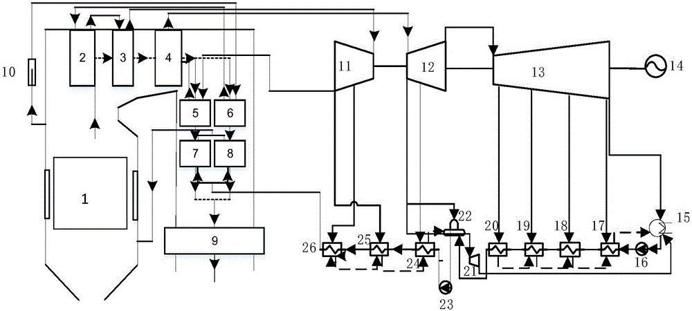
[0027] figure 1It is a schematic flow diagram of a conventional coal-fired power generation system, which serves as a benchmark system. The feed water passes through 8# low temperature heater 17, 7# low temperature heater 18, 6# low temperature heater 19, 5# low temperature heater 20, 3# high temperature heater 24, 2# high temperature heater 25 and 1# high temperature heater 26 After preheating, it enters the low-side economizer 7 and the low-pass side economizer 8 for further preheating, and then enters the water wall of the boiler 1 to be heated and evaporated. After steam-water separation by the steam-water separator 10, the superheated steam passes through the low-temperature The superheater 6,...


PUM


Abstract

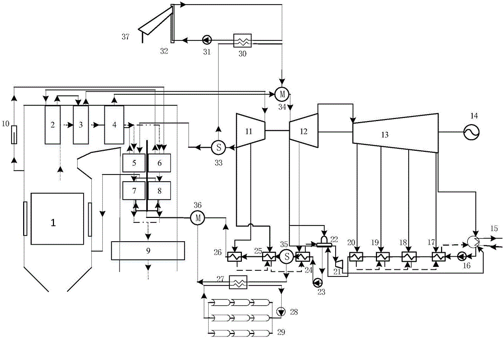
The invention relates to a coal-fired power generation system simultaneously integrating a slot type solar heat collecting system and a tower type solar heat collecting system. The tower type solar heat collecting system is combined with a reheated steam side of the coal-fired power generation system, and the slot type solar heat collecting system is combined with a high-temperature heater side of the coal-fired power generation system. In case of receiving solar radiation, the slot type solar heat collecting system replaces a partial heated surface of a 1# high-temperature heater and a partial heated surface of a 2# high-temperature heater to reduce steam extraction capacity of a high-pressure cylinder of a steam turbine according to the solar radiation condition; and meanwhile, the tower type solar heat collecting system replaces a partial heated surface of the reheated steam side, so that stable and safe operation of a boiler unit is guaranteed. When solar radiation changes, complementary operation of the solar heat collecting systems and a conventional thermal-power coal-fired unit is realized by regulating feedwater flow at a slot type solar heat collecting system side and cold regenerated steam flow at a tower type solar heat collecting system side. The invention discloses a more stable and practical integration idea for energy-saving reconstruction of a conventional coal-fired power plant.

Description

technical field [0001] The invention belongs to the technical field of integrated power generation of solar energy and coal-fired thermal power units, and in particular relates to a coal-fired power generation system that simultaneously integrates trough-type and tower-type solar heat collection systems. Background technique [0002] At present, the efficiency of my country's new high-parameter, large-capacity supercritical and ultra-supercritical units has approached or reached the international advanced level. The way to further increase parameters and increase capacity to improve unit efficiency will be restricted by technical bottlenecks such as materials. Purely from the internal considerations of the unit, the potential for further reduction of coal consumption is already very small. And in the conventional coal-fired power generation system, the massive consumption of fossil energy has caused environmental problems such as smog and acid rain, and also produced a large ...

Claims


Application Information

Patent Timeline
IPC IPC(8): F01K11/02F01K3/18F01K17/02F22B1/00
CPCF01K3/18F01K11/02F01K17/02F22B1/006
Inventor 段立强贾时轮庞力平袁明野吕志鹏
Owner NORTH CHINA ELECTRIC POWER UNIV (BAODING)
Learn More