
Method and device for pulsed eddy current testing weld seam

A pulsed eddy current and sensor technology, applied in the direction of measuring devices, instruments, scientific instruments, etc., can solve problems such as difficult implementation, threats to the human body, and reduced reliability, and achieve simple and easy operation of equipment, high detection efficiency, and high detection efficiency Effect

Active Publication Date: 2021-11-19
TIANJIN YINKE XINCHUANG TECH CO LTD
View PDF4 Cites 0 Cited by
  • Summary
  • Abstract
  • Description
  • Claims
  • Application Information

AI Technical Summary

Problems solved by technology

These technologies have their own advantages. For example, the magnetic particle method is very simple to be applied on site, and can directly detect surface defects. However, if the surface of the inspected workpiece is coated or wet, the reliability of the detection will be greatly reduced, so the coating must be removed first, and the surface must be dried. ; Penetration method is very sensitive to the detection of surface opening cracks, but it is not ideal for workpieces with coating and moisture on the surface, and the judgment of defects depends on the experience of technicians; ultrasonic method is very effective for the detection of defects under the surface of workpieces, but Coupling agents are required for detection, and the efficiency is low, and the determination of defects also depends on the experience of technicians; the ray method is very effective for detection under the surface layer, but ray radiation threatens the human body, and safety protection must be carried out for detection, and some working conditions are not easy implementation; conventional eddy current technology is very sensitive to surface opening cracks, and can also carry out detection work in harsh environments such as surface coatings, humidity, and underwater, but the judgment of defects also depends on the experience of technicians

Method used

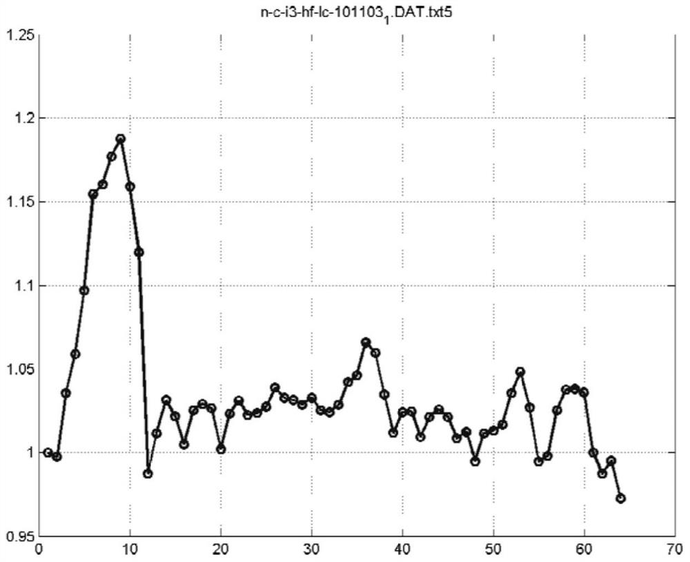

Image

  • Method and device for pulsed eddy current testing weld seam

Examples


Embodiment 1

[0035] Ultrasonic test block with weld defects, weld width 2cm, the wall thickness of 11.0mm, 20 # steel, formed with cracks, incomplete penetration, porosity defects in three positions. Temperature room temperature detection section 0.80m, along the weld inspection. Detecting the following steps:

[0036] 1) selection of a diameter of 20mm, the number of turns of the sensor 200 × 500.

[0037] 2) The region directly above the sensor line is set by the test apparatus transmitting and receiving a control pulse eddy PDA, 1Hz square wave to select a transmission signal detection.

[0038] 3) Select an arbitrary position of the line segment, ultrasonic thickness measurement, the thickness values ​​detected record. To take the sensor detecting the position of the pulsed eddy current, the ultrasonic wave value input PAD value, the calibration factor is obtained.

[0039] 4) start the detection mode, the sensor will move slowly along the line region to be diagnosed until the end of the a...


PUM


Abstract

The invention discloses a method and a detection system for pulsed eddy current detection of weld defects, comprising the following steps: selecting a suitable sensor; using a pulsed eddy current generator to send a square wave signal as a detection emission signal; continuously moving the sensor to collect the position of continuous parts Data; extract continuous curves of voltage values ​​at different depth-related positions; calculate the rate of change of induced voltage at a special position; determine the position and depth of the defect. The method of the present invention uses pulsed eddy current technology to detect weld defects, and the detection efficiency is high; it does not need surface treatment and is not affected by the lift-off effect; the use of pulsed eddy current to detect welds is not restricted by professional technical experience, and the equipment The operation is simple and easy. The device and method of the invention make the detection of the weld seam more efficient and accurate, and are more suitable for on-line use at the customer's production site.

Description

Technical field [0001] The present invention relates to non-destructive testing technique, particularly to a method and apparatus for pulsed eddy current testing of welds. Background technique [0002] Currently used in nondestructive testing of weld quality inspection method of magnetic powder, penetration, ultrasonic, eddy current conventional radiation and other detection techniques. These techniques have their advantages, such as a magnetic field application method is very simple, direct detection of surface defects, but if the subject workpiece surface with a coating or moisture, will significantly reduce the reliability of the detection, it is necessary to remove the coating, dry surface ; penetration opening surface crack detection method of high sensitivity, but the surface of the coated workpiece is not ideal and humid, and depends on the experience of the art the determination of the defect; ultrasonic workpiece detecting subsurface defects is effective but couplant req...

Claims


Application Information

Patent Timeline
Patent Type & Authority Patents(China)
IPC IPC(8): G01N27/90
CPCG01N27/9046
Inventor 陶建涛籍康张莹
Owner TIANJIN YINKE XINCHUANG TECH CO LTD
Learn More