A method and device for generating high-voltage pulse radar signals based on an optically induced switch

A radar signal, high-voltage pulse technology, applied in measurement devices, re-radiation of electromagnetic waves, reflection/re-radiation of radio waves, etc. Radar equipment and detection technology promotion and popularization to achieve the effect of fast rise time, high stability and repeatability

Active Publication Date: 2018-10-02
ZHEJIANG UNIV
View PDF3 Cites 0 Cited by
  • Summary
  • Abstract
  • Description
  • Claims
  • Application Information

AI Technical Summary

Problems solved by technology

Half of the common electromagnetic pulse signal circuit generation circuit uses semiconductor avalanche diodes, step diodes and other multi-stage series connections to realize high-voltage radar wave pulse signals. There are parameter differences, delay out-of-sync, and parasitic parameters among individual devices, which will cause the pulse width of the radar pulse waveform to widen, and at the same time cause the tail of the high-voltage pulse signal
[0004] At present, the vast majority of ground penetrating radar equipment used in actual engineering in China relies on foreign imports, but judging from the current application situation, there are still big problems and technical bottlenecks in the application of ground penetrating radar in engineering detection, first of all The high price of equipment limits the promotion and popularization of ground penetrating radar equipment and detection technology. Another very important reason is that the application and selection of equipment are very dependent on the characteristics of the target to be detected. For example, different target detection depths and different target sizes should choose different series. Or radars of different frequency bands; technically speaking, the high-voltage short pulse generation technology with a certain repetition frequency is an important key to the ground-penetrating radar detection technology based on pulse signals, and the characteristics of ground-penetrating radars of different models and different frequency bands correspond to specific emission The pulse width of radar waves, such as the 500MHz band impacting the radar, corresponds to a pulse width close to 1 nanosecond; moreover, there is an inherent contradiction between the radar detection resolution and the detection range. Although the high-frequency radar has a higher resolution, its The penetration depth is very limited, generally 400MHz penetration depth is 4 meters, while the typical 1.6GHz radar penetration depth is only 0.5 meters

Method used


Image

  • A method and device for generating high-voltage pulse radar signals based on an optically induced switch
  • A method and device for generating high-voltage pulse radar signals based on an optically induced switch
  • A method and device for generating high-voltage pulse radar signals based on an optically induced switch

Examples


Embodiment Construction

[0030] In order to describe the present invention more specifically, the technical solution of the present invention will be described in detail below in conjunction with the accompanying drawings and specific embodiments.

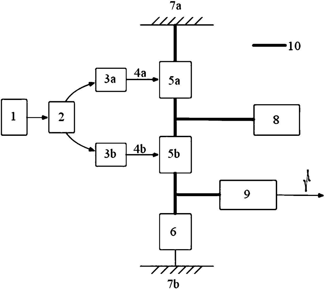
[0031] A method for generating a high-voltage pulse radar signal based on an optically induced switch, comprising the steps of:

[0032]1) Generate an induced laser pulse signal, which is divided into two paths through an optical coupler;

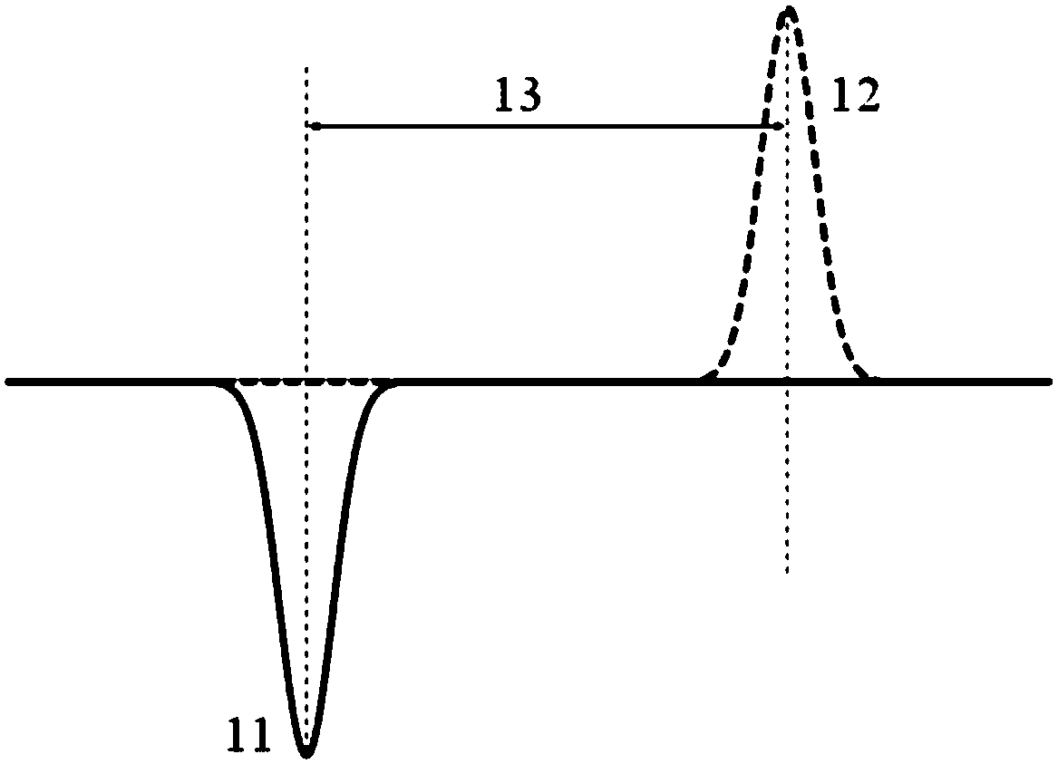
[0033] 2) Through the optical induction switch, the two induction pulse signals generate forward wave and reverse wave;

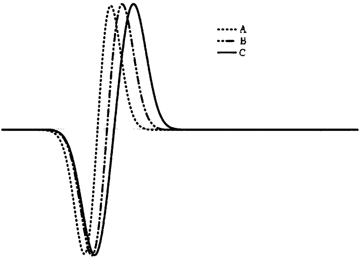
[0034] 3) The relative time delay between the forward wave and the reverse wave is adjusted by the delay control module to generate a radar signal with adjustable pulse width.

[0035] Such as figure 1 As shown, the device for generating a high-voltage pulse radar signal based on an optical inductive switch includes an inductive laser control circuit and a pulse generation circuit; the inductive la...


PUM


Abstract

The invention discloses a method and device for generating a high-voltage pulse radar signal based on a photo-induced switch. The method comprises the following steps of 1) generating an induced laser pulse signal which is divided into two paths by an optical coupler; 2) enabling the two paths of the induced laser pulse signal to generate a forward wave and a backward wave by a photo-induced switch; and 3) adjusting the relative time delay of the forward wave and the backward wave through a time delay control module to produce a radar signal with adjustable pulse width. The device comprises: an induced laser control circuit which outputs the generated induced laser pulse as the two paths of the induced laser pulse signal; a pulse generating circuit which generates two pulses in opposite directions and outputs a radar signal with adjustable pulse width. The invention has the advantages of higher stability and repeatability, enables the generated radar signal to have better quality and smaller waveform tailing, allows automatic or manual adjustment of the pulse width of the ground penetrating radar signal in actual detection, and achieves highly adaptive and targeted detection of best resolution.

Description

technical field [0001] The invention belongs to the technical field of ground penetrating radar, and in particular relates to a method and a device for generating high-voltage pulse radar signals based on an optical induction switch. Background technique [0002] The mechanism of ground-penetrating radar equipment and technology for underground target detection is to analyze and infer according to the echo signal amplitude, time, frequency characteristics and other parameters by emitting high-frequency electromagnetic pulse waves, using the difference in electrical parameters between the underground target and the surrounding medium. Information such as the spatial position, depth and size of underground targets. GPR is an efficient shallow geophysical detection technology. Different from airsonde radar, the frequency used by GPR is generally lower than that of the former. Its theoretical research is mainly on the propagation of electromagnetic waves in lossy media. Uniform...

Claims


Application Information

Patent Timeline
Patent Type & Authority Patents(China)
IPC IPC(8): G01S7/282G01S7/484G01S13/88G01S17/88
CPCG01S7/282G01S7/484G01S13/885G01S17/88
Inventor 马川江
Owner ZHEJIANG UNIV
Why Eureka
Try Eureka