
Vacuum negative pressure nano-imprinting method

A technology of nanoimprinting and vacuum negative pressure, applied in nanotechnology, optics, optomechanical equipment, etc., can solve the problems of template deformation, easy to be filled, no structure transfer, etc., to achieve complete filling, avoid contact with air bubbles, and protect damaged effect

Inactive Publication Date: 2016-12-07
苏州天仁微纳智能科技有限公司
View PDF4 Cites 3 Cited by
  • Summary
  • Abstract
  • Description
  • Claims
  • Application Information

AI Technical Summary

Problems solved by technology

[0005] 1. Under the pressure of the imprint template, the nanostructure on the surface is easily damaged
[0006] 2. After the imprint template is in contact with the imprint material, a small amount of gas will be sealed in the gaps of the imprint template structure. This part of the gas will affect the filling of the imprint template structure by the imprint material, for example, resulting in incomplete filling of the structure and cracks on the surface. sunken
[0007] 3. This part of the gas needs to penetrate into the imprinting material or the imprinting template (such as using a silicone rubber template) through a long waiting time. This waiting time greatly limits the production capacity of the imprinting process
[0008] 4. The imprinting material is squeezed into the gap of the embossing template structure by pressure. When the template structure is uneven, small structures are easy to be filled, and large structures need higher pressure to be filled, which is easy to cause structure filling uneven problem
[0009] 5. When using a soft embossing template, such as a silicone rubber template, the pressure of the embossing is likely to cause deformation of the template, which affects the accuracy of the imprinting structure and the alignment accuracy of the template graphics
[0010] 6. When the surface of the substrate is uneven, the air bubbles will be sealed in the uneven area, and there will be no structural transfer in the early part

Method used


Image

  • Vacuum negative pressure nano-imprinting method

Examples


Embodiment Construction

[0029] The specific implementation manners of the present invention will be further described below in conjunction with the drawings and examples. The following examples are only used to illustrate the technical solution of the present invention more clearly, but not to limit the protection scope of the present invention.

[0030] The technical scheme of concrete implementation of the present invention is:

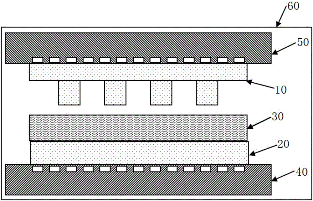
[0031] like figure 1 As shown, a vacuum negative pressure nanoimprinting method comprises the following steps:

[0032] 1) Prepare a soft nanoimprint template 10, a substrate 20 and a nanoimprint material; the material of the soft nanoimprint template 10 is polydimethylsiloxane (PDMS), polytetrafluoroethylene (Teflon) or Perfluoropolyether (PFPE); the nanoimprint material adopts a polymer colloid that can be cured by ultraviolet exposure, and the viscosity of the polymer colloid is lower than 50mPa·s;

[0033] 2) Coating the polymer colloid on the top surface of the sub...


PUM

PropertyMeasurementUnit
viscosityaaaaaaaaaa

Abstract

The invention provides a vacuum negative pressure nano-imprinting method. A siphonic effect generated in an environment at a vacuum degree of less than 500Pa is strengthened; and the surface structure of a nano-imprinting template is automatically filled with a liquid nano-imprinting material, so that the shortcomings of limitation on the imprinting precision caused by contact bubbles, uneven structural filling, slow filling speed, deformation of the imprinting template and the like are avoided.

Description

technical field [0001] The invention relates to a vacuum negative pressure nano imprint method. Background technique [0002] Nanoimprint technology is a micro-nano processing technology that transfers graphics to corresponding substrates through templates. The transfer medium is usually a layer of imprinting material, usually a polymer film, which is used by hot pressing or irradiation. Its structure hardens to preserve the transferred pattern. This technology breaks through the difficulties of traditional lithography in the process of reducing the feature size, and has the characteristics of high resolution, low cost and high yield. Widely used in semiconductor manufacturing, MEMS, biochips, biomedicine and other fields. [0003] During the imprint structure transfer process, the integrity of the imprint material filling the surface structure of the imprint template determines the quality of the imprint results, and the time required for the imprint material to fill the ...

Claims


Application Information

Patent Timeline
Patent Type & Authority Applications(China)
IPC IPC(8): G03F7/00B82Y40/00
CPCB82Y40/00G03F7/0002
Inventor 冀然
Owner 苏州天仁微纳智能科技有限公司
Learn More