Reflecting-type super diffraction line focusing device based on metal strip-shaped antenna array

A strip antenna and line focusing technology, applied in the field of optical imaging and optical focusing, can solve the problems of large focal spot size, limited application range, high side lobe ratio, etc., achieve low side lobe peak ratio, improve focusing performance, and improve focus energy effect

Active Publication Date: 2016-12-07
CHONGQING UNIV
View PDF2 Cites 9 Cited by
  • Summary
  • Abstract
  • Description
  • Claims
  • Application Information

AI Technical Summary

Problems solved by technology

[0006] According to the focusing performance of the existing transmissive lenses, the utilization rate of light energy is generally low, and the transmission efficiency does not exceed 20%. There are two vertical linearly polarized lights, so one of the linearly polarized lights needs to be filtered out by a polarizer during the experiment, which not only reduces the light energy utilization rate but also affects the focusing performance of the device
Although the existing reflective focusing devices have high focusing efficiency, their focal spot size is generally large and the sidelobe ratio is high, and super-diffraction focusing has not been realized, which greatly limits the scope of application.

Method used


Image

  • Reflecting-type super diffraction line focusing device based on metal strip-shaped antenna array
  • Reflecting-type super diffraction line focusing device based on metal strip-shaped antenna array
  • Reflecting-type super diffraction line focusing device based on metal strip-shaped antenna array

Examples


Embodiment Construction

[0043] The technical solution of the present invention will be further described below in conjunction with the accompanying drawings.

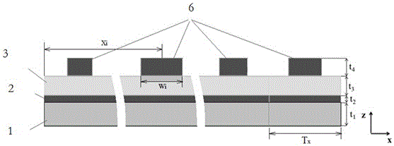
[0044] see image 3 , the reflective superdiffraction line focusing device is used to realize far-field superdiffraction line focusing, including a substrate 1, a metal film layer 2, a dielectric layer 3 and a metal strip antenna array 6. For the incident light wavelength λ, the substrate 1 is of thickness t 1 transparent medium material. The metal film layer 2 has a thickness of t 2 A film of metallic material on a substrate. The dielectric layer 3 has a thickness of t 3 The dielectric film is located on the metal film layer. The metal strip antenna array 6 is located on the dielectric layer 3 .

[0045] Such as Figure 4 A schematic diagram of the metal strip antenna array is given, and a three-dimensional coordinate system is established with the dielectric layer as the reference plane. The metal strip antenna array 6 is composed of ...


PUM


Abstract

The invention provides a reflecting-type super diffraction line focusing device based on a metal strip-shaped antenna array. The device sequentially comprises the metal strip-shaped antenna array, a dielectric layer, a metal membrane layer and a substrate layer. Each metal strip-shaped antenna array unit is of a Y-direction array structure formed by arranging metal strip-shaped antennas in the Y direction by taking Ty as a cycle, and the metal strip-shaped antenna array units are arranged in the X direction by taking Tx as a cycle to form the metal strip-shaped antenna array. For the given incident light wavelength gamma, regulation and control over the amplitude and the phase of reflected light in the space plane are achieved by selecting a metal material, a material of the dielectric layer and the thickness of the metal strip-shaped antennas and changing the length L and the width W of metal strips, the length Li and the width Wi of the i metal-shaped antenna of which the center is located at xi are obtained according to amplitude space distribution A(xi) and phase space distribution P(xi), and then a far-field super diffraction line focusing function on the reflected light is achieved. According to device, the diffraction limit can be broken through, the focal spot size smaller than the diffraction limit is achieved, the sidelobe peak ratio is low, and the peak strength is high.

Description

technical field [0001] The invention belongs to the field of light focusing and light imaging, in particular to a reflective superdiffraction line focusing device. Background technique [0002] In micro-nano optical devices, superdiffractive focusing lenses usually use sub-wavelength structure arrays to control the amplitude and phase of incident electromagnetic waves. However, it is difficult for transmissive sub-wavelength structures to take into account high amplitude transmittance and large phase control range, resulting in low transmittance of the device. , which greatly limits its application. The reflective sub-wavelength structure can realize a wide range of phase adjustment of the incident light under the premise of ensuring a high transmittance, which can effectively improve the focusing efficiency and focusing performance of the focusing device, such as: increasing the focusing energy and reducing the focusing light field sidelobe, reducing the focal spot size, e...

Claims


Application Information

Patent Timeline
Patent Type & Authority Applications(China)
IPC IPC(8): H01Q15/02
CPCH01Q15/02
Inventor 陈刚温中泉李语燕余安平
Owner CHONGQING UNIV
Why Eureka
Try Eureka