Direct-driven permanent-magnet motor

A technology for permanent magnet motors and machine bases, applied in magnetic circuits, electric components, electrical components, etc., can solve the problems of uneven loss of the upper and lower layers of the winding and the left and right layers, increase the burden of rotor heat dissipation, and unfavorable rotor heat dissipation, etc., to reduce the stator Reduce copper consumption and heat generation, improve product market competitiveness, and fix simple and reliable effects

Inactive Publication Date: 2016-12-07
中国船舶重工集团公司第七一二研究所
View PDF7 Cites 9 Cited by
  • Summary
  • Abstract
  • Description
  • Claims
  • Application Information

AI Technical Summary

Problems solved by technology

The application of low-power and low-dissipation windings is more common. Generally, a view is that the rotor and stator of permanent magnet synchronous motors rotate synchronously, and the loss in the rotor is often ignored, especially the loss of the rotor magnet. However, in the large-torque forming winding, the actual The situation is due to the cogging effect of the concentrated fractional slot, the mutual influence of the winding harmonic magnetic potential and the harmonic current, especially the low-order harmonic influence will cause eddy current loss on the rotor, and there are upper and lower layers and left and right layers of the winding in the stator slot The phenomenon of uneven loss, although the eddy current loss of the rotor is smaller than the copper loss and iron loss, but if no measures are taken, even such a small loss may cause a high temperature rise, which will cause local demagnetization of the permanent magnet, and reduce the performance of the motor. damage, and the uneven loss of conductors in the stator slot will also lead to serious local heating
[0008] At the same time, the fixing method of the radial surface-mounted inner rotor magnet, whether it is as mentioned in the above patent, uses fixing screws, anaerobic adhesive, insulating layer, high-density glass fiber cloth and epoxy resin adhesive layer to surround and seal the entire outer surface of the rotor. The composite fixing method is still the jacket sleeve method. The former is not conducive to the heat dissipation of the rotor, and the latter generates heat itself, which increases the heat dissipation burden of the rotor. There are certain problems.

Method used


Image

  • Direct-driven permanent-magnet motor
  • Direct-driven permanent-magnet motor
  • Direct-driven permanent-magnet motor

Examples


Embodiment 1

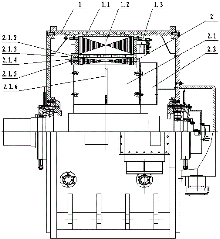
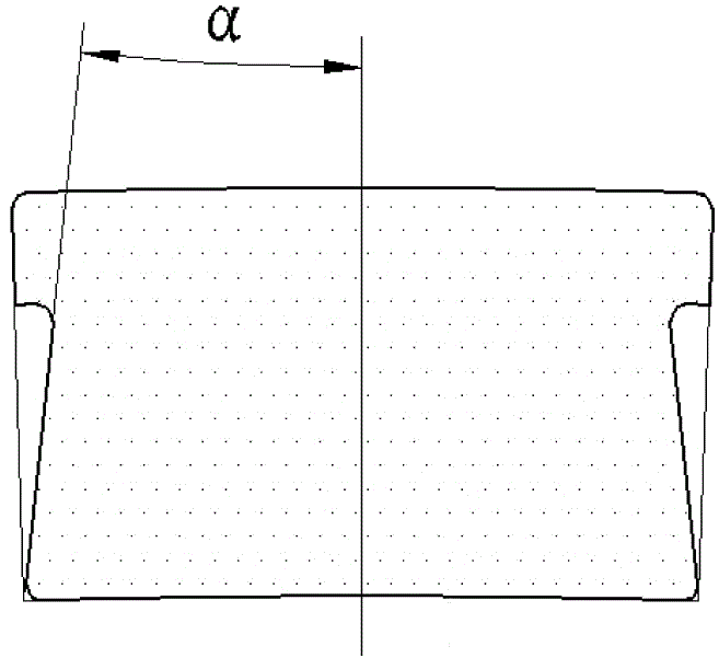
[0028] refer to figure 1 As shown, the present invention discloses a low-speed high-torque direct-drive permanent magnet motor, including a stator 1 and a rotor 2, and the stator 1 includes a water jacket base 1.1 and a stator core fixed on the water jacket base 1.1 1.2, the surface of the stator core 1.2 is regularly provided with a plurality of annular opening slots, and the stator winding 1.3 is arranged in the opening slots; the rotor 2 includes a rotor body 2.1 with a bracket and a rotor fan 2.2 ; The rotor body 2.1 includes a rotating shaft 2.1.6 and a rotor core 2.1.3 arranged on the rotating shaft 2.1.6, and the rotor core 2.1.3 is formed by interleaving and laminating a plurality of fan-shaped rotor punches, A plurality of tapered grooves 2.1.3.1 with tapered cross-sections are arranged on the outer circumference of the fan-shaped rotor punch according to the law, and the tapered grooves 2.1.3.1 are provided with matching cross-sections that are tapered T-shaped The ...

Embodiment 2

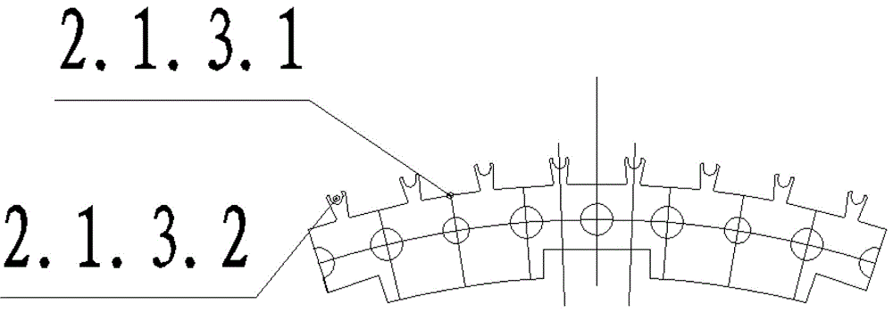
[0031] The difference from Example 1 is that a plurality of U-shaped through-holes 2.1.3.2 are regularly arranged on the outer circumference of the fan-shaped rotor punching piece, and the U-shaped through-holes 2.1.3.2 are arranged on adjacent Between two tapered grooves 2.1.3.1.

[0032] The tapered groove 2.1.3.1 and the U-shaped through hole 2.1.3.2 are punched directly from fan-shaped silicon steel sheets, and the rotor magnetic circuit and the yoke are formed after staggered lamination. The tapered groove 2.1.3.1 is used for magnetic steel installation. 2.1.3.2 The U-shaped through hole 2.1.3.2 The width and depth of the U-shaped hole depend on the one hand on the loss of the allowable magnetic flux leakage to the torque under the action of magnetic isolation, and on the other hand depend on the design requirements of the rotor 2 ventilation path, "U The unique design of the "shaped through hole simultaneously plays the double effect of magnetic isolation and ventilation...

Embodiment 3

[0034] The difference from Example 1 is that the fan-shaped rotor punch is regularly provided with a plurality of circular through holes, and the two ends of the rotor core 2.1.3 are provided with rotor tooth pressure plates 2.1.4, one of which is The outer side of the rotor tooth pressure plate 2.1.4 is provided with a rotor pressure plate 2.1.2, and the corresponding positions of the rotor tooth pressure plate 2.1.4 and the rotor pressure plate 2.1.2 are provided with through holes, and the circular through hole and the through hole A tension screw 2.1.5 is arranged in the hole. The rotor iron core 2.1.3 is positioned on the outer circle with the tooling when the fan-shaped rotor punches are stacked, and is fixed as a whole by tightening the screw rod 2.1.5, the rotor tooth pressure plate 2.1.4 and the rotor pressure plate 2.1.2.

[0035] The stator winding of the low-speed direct-drive motor of the present invention heats up evenly, and the rotor magnetic steel is fixed sim...


PUM


Abstract

The invention discloses a direct-driven permanent-magnet motor. The direct-driven permanent-magnet motor comprises a stator and a rotor, wherein the stator comprises a water jacket engine base and a stator iron core, the stator iron core is fixed on the water jacket engine base, a plurality of annular opening grooves are formed in a surface of the stator iron core according to a rule, stator windings are arranged in the opening grooves, the rotor comprises a rotor body with a support and a rotor fan, the rotor body comprises a rotation shaft and a rotor iron core, the rotor iron core is arranged on the rotation shaft and is formed by laminating a plurality of fan-shaped rotor punching sheets in a staggered way, a plurality tapered grooves are formed in the outer circumference of each fan-shaped rotor punching sheet, and T-shaped magnetic steel with a tapered cross section is arranged in each tapered groove. In the direct-driven permanent-magnet motor, the stator windings uniformly generate heat, the magnetic steel is simple and reliable in fixing, a glass fiber or a jacket sleeve is not needed to be bonded, the rotor body and the magnetic steel are low in heat generation, and the reliability and the safety of the magnetic steel are improved; and meanwhile, the motor process is further simplified, the motor cost is reduced, and the market competiveness of a product is improved.

Description

technical field [0001] The invention belongs to the technical field of motor manufacturing, in particular to a radial surface-mounted inner rotor direct-drive permanent magnet motor, which is mainly used in mine conveying machinery. Background technique [0002] Mining machinery such as scraper conveyors, belt conveyors, elevators, ball mills, etc. are all low-speed high-torque transmission systems. At present, the system is generally composed of high-power asynchronous motors, reducers and hydraulic couplings. Due to the existence of reducers and hydraulic couplings and the phenomenon of large horses and small carts often appearing in the driving motor, the transmission system has disadvantages such as low efficiency, high power consumption, unstable starting, difficult starting with heavy loads, and heavy maintenance workload. cumbersome. In addition, the use of a multi-stage transmission system results in a large weight of the entire system and low torque and power densi...

Claims


Application Information

Patent Timeline
Patent Type & Authority Applications(China)
IPC IPC(8): H02K1/16H02K1/27H02K1/32H02K5/24
CPCH02K1/165H02K1/276H02K1/32H02K5/24
Inventor 周贵厚张立春熊用徐磊许晓晖
Owner 中国船舶重工集团公司第七一二研究所
Why Eureka
Try Eureka