
Aerated concrete cutting device and working method thereof

A technology of aerated concrete and cutting device, which is applied in the direction of working accessories, stone processing equipment, stone processing tools, etc., and can solve problems such as easy damage of steel saws, breaking of lifting and transportation, and affecting the health of workers

Inactive Publication Date: 2016-12-14
XUZHOU UNIV OF TECH
View PDF8 Cites 2 Cited by
  • Summary
  • Abstract
  • Description
  • Claims
  • Application Information

AI Technical Summary

Problems solved by technology

At present, the steel plate saw is often used to saw off the aerated concrete block along the pre-marked cutting line at the construction site. Although it is neat and uniform, the work efficiency is low, and the steel plate saw is easy to damage, especially during the sawing process, the dust generated greatly affects the operation. staff health
[0005] In addition, the current production of aerated concrete adopts automatic turning and step-by-step mechanical cutting technology, which is easy to cause many defects such as turning fracture, lifting fracture, cutting fracture, etc., which greatly increases labor intensity and production cost.

Method used


Image

  • Aerated concrete cutting device and working method thereof
  • Aerated concrete cutting device and working method thereof
  • Aerated concrete cutting device and working method thereof

Examples


Embodiment 1

[0063] The transverse cutting line 4-4-4 and the longitudinal cutting line 5-5-4 of the present invention are manufactured according to the following steps, and are calculated in parts by weight:

[0064] Step 1: Add 1850 parts of ultrapure water with a conductivity of 5.75μS / cm into the reactor, start the stirrer in the reactor at a speed of 64rpm, start the heating pump, and raise the temperature in the reactor to 120°C; add in sequence 45 parts of cis-chloroformic acid-4-(1,1-dimethylethyl)cyclohexyl ester, peroxy[(1-methylethylene)di-4-cyclohexyl-1-ylidene]tetra( 1,1-dimethylethyl) 54 parts, N-[4-[bis(p-ethylenediaminophenyl)methylene]-2,5-cyclohexadiene-1-ylidene]-N-ethane 26 parts of ethylamine chloride, stirred until completely dissolved, adjusted the pH value to 5.7, adjusted the speed of the agitator to 124rpm, the temperature was 130°C, and the esterification reaction was carried out for 10 hours;

[0065] Step 2: Take 15 parts of ethyl sulfate of N-ethyl-N,N-dimeth...

Embodiment 2

[0070] The transverse cutting line 4-4-4 and the longitudinal cutting line 5-5-4 of the present invention are manufactured according to the following steps, and are calculated in parts by weight:

[0071] Step 1: Add 2250 parts of ultrapure water with a conductivity of 6.55μS / cm into the reactor, start the stirrer in the reactor at a speed of 96rpm, start the heating pump, and raise the temperature in the reactor to 150°C; add in order Cis-chloroformic acid-4-(1,1-dimethylethyl)cyclohexyl ester 65 parts, peroxy[(1-methylethylene)di-4-cyclohexyl-1-ylidene]tetra( 1,1-dimethylethyl) 85 parts, N-[4-[bis(p-ethylenediaminophenyl)methylene]-2,5-cyclohexadiene-1-ylidene]-N-ethane 41 parts of ethylamine chloride were stirred until completely dissolved, the pH was adjusted to 7.5, the speed of the agitator was adjusted to 155rpm, the temperature was 175°C, and the esterification reaction was carried out for 18 hours;

[0072] Step 2: Take 36 parts of ethyl sulfate of N-ethyl-N,N-dimethyl...

Embodiment 3

[0077] The transverse cutting line 4-4-4 and the longitudinal cutting line 5-5-4 of the present invention are manufactured according to the following steps, and are calculated in parts by weight:

[0078] Step 1: Add 2670 parts of ultrapure water with a conductivity of 8.25μS / cm into the reactor, start the stirrer in the reactor at a speed of 115rpm, start the heating pump, and raise the temperature in the reactor to 180°C; add in sequence 83 parts of cis-chloroformic acid-4-(1,1-dimethylethyl)cyclohexyl ester, peroxy[(1-methylethylene)di-4-cyclohexyl-1-ylidene]tetra( 1,1-dimethylethyl) 120 parts, N-[4-[bis(p-ethylenediaminophenyl)methylene]-2,5-cyclohexadiene-1-ylidene]-N-ethane 56 parts of ethylamine chloride, stirred until completely dissolved, adjusted the pH value to 8.5, adjusted the speed of the agitator to 185rpm, the temperature was 220°C, and the esterification reaction was carried out for 24 hours;

[0079] Step 2: Take 63 parts of ethyl sulfate of N-ethyl-N,N-dime...


PUM


Abstract

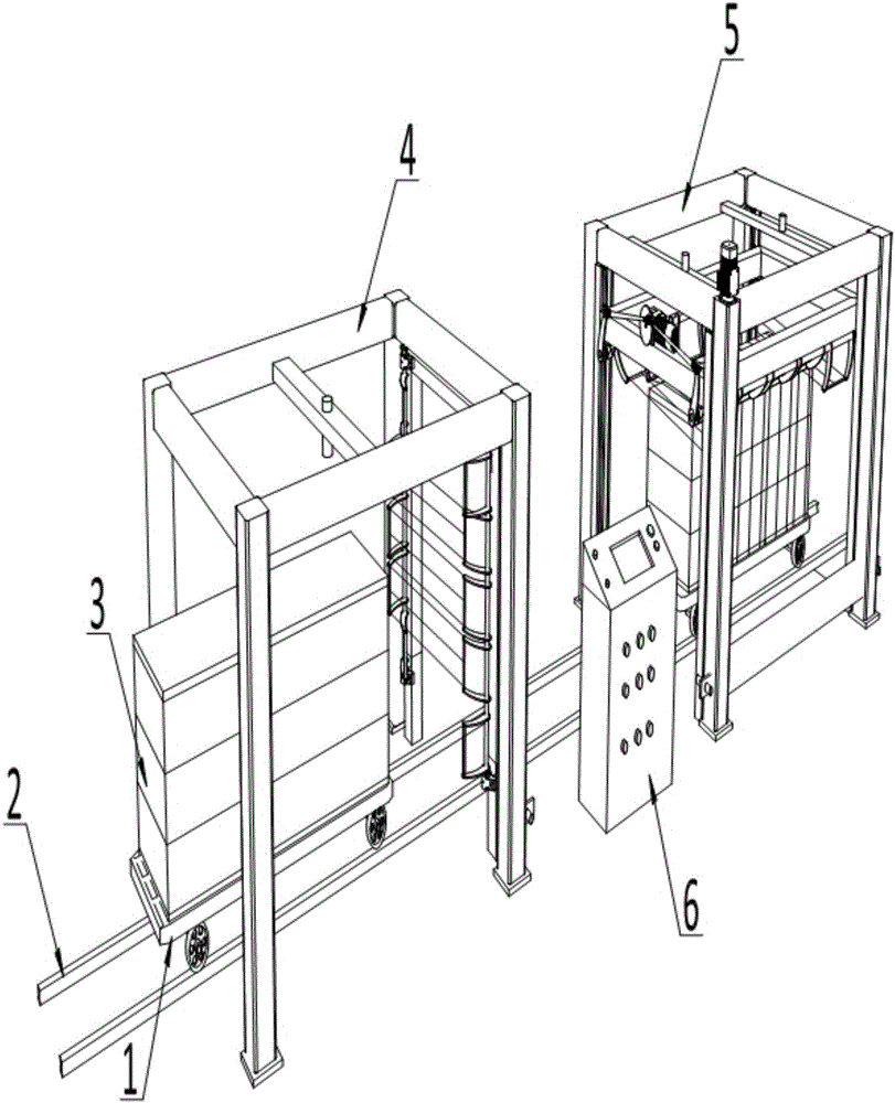
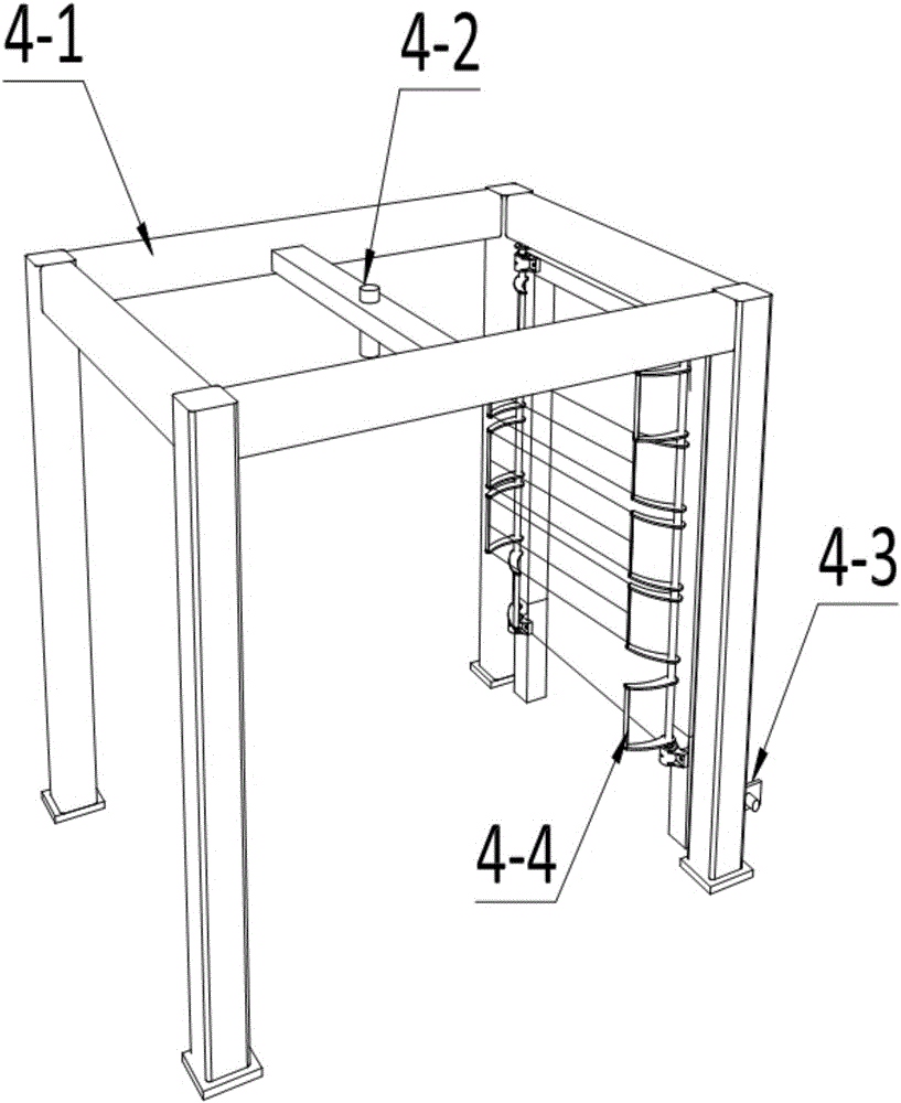
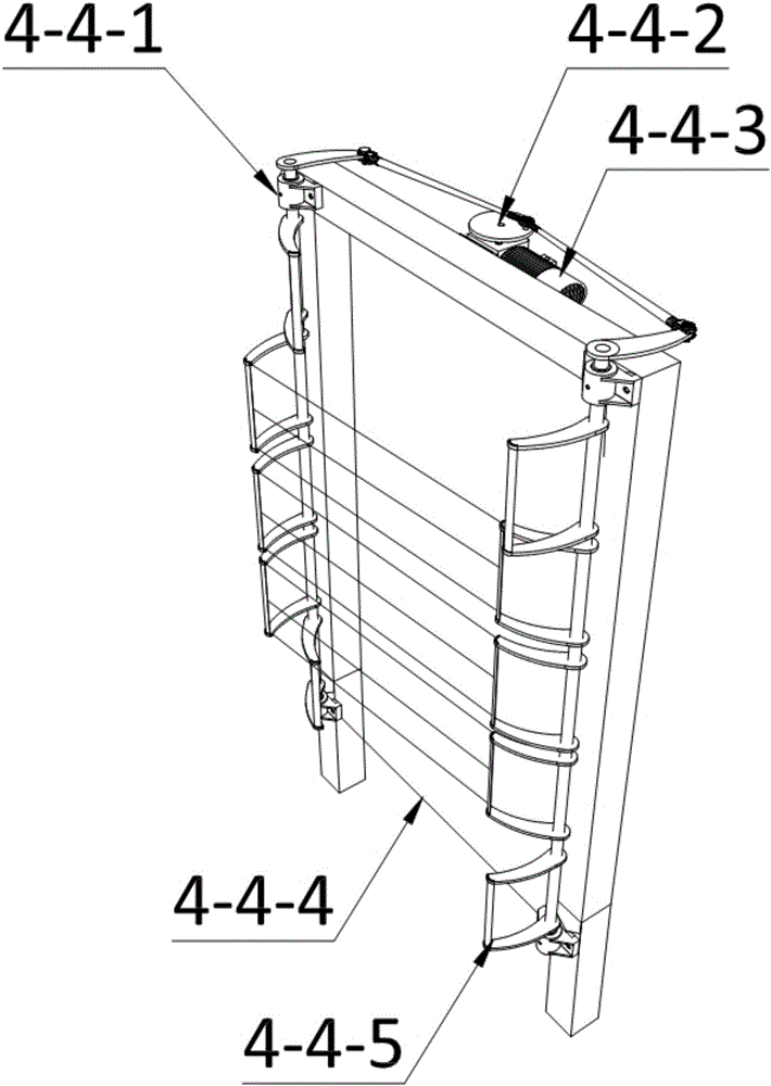
The invention discloses an aerated concrete cutting device and a working method thereof. The aerated concrete cutting device is composed of a material trolley, steel rails, to-be-treated materials, a transverse cutting device, a longitudinal cutting device and an electric control center, wherein the steel rails are fixedly paved on the ground, the material trolley is arranged on the steel rail, and the material trolley is driven by a motor; the to-be-treated materials, which are placed on the material trolley, are of rectangular structures; the transverse cutting device and the longitudinal cutting device interpenetrate through the upper parts of the steel rails; and the electric control center is located between the transverse cutting device and the longitudinal cutting device. The aerated concrete cutting device disclosed by the invention is simple in structure, compact in machine type structure and little in space requirement; the device is high in degree of automation, and the device is simple and convenient to operate and control in the whole cutting process which is automatically finished; the device can effectively eliminate breakage and crack defects generated in a green body machining process.

Description

technical field [0001] The invention belongs to the field of building material equipment, and in particular relates to an aerated concrete cutting device. Background technique [0002] The aerated concrete industry has a history of more than 40 years in my country, and has formed a complete system including production, equipment manufacturing, supporting material production and scientific research and design. According to incomplete statistics, there are currently nearly 600 manufacturers of aerated concrete products nationwide, with a total designed annual production capacity of more than 46.5 million cubic meters. The aerated concrete industry has become an important force in building energy conservation and wall material innovation in my country, and has made great contributions to circular economy and low-carbon life. [0003] Due to the advantages of light weight and porous insulation, aerated concrete blocks are currently widely used in filling walls of buildings. How...

Claims


Application Information

Patent Timeline
IPC IPC(8): B28D1/22B28D7/00B28D7/04C08L33/14C08K5/101C08K5/14C08K5/18C08K5/41C08K5/39C08J3/28
CPCB28D1/22B28D7/00B28D7/005B28D7/04C08J3/28C08J2333/14C08K5/101C08K5/14C08K5/18C08K5/39C08K5/41C08L33/14
Inventor 张志军曹露春毕晓茜吕芳礼
Owner XUZHOU UNIV OF TECH
Learn More